
Tags
With a little more time on my hands this past year, some regularly-conceived flights of fancy that might previously have withered as precisely that, have found themselves transforming to intent and then action. The existence of a 3D printer in my workshop, purchased as the central component in the 3D-printed watch-cleaning machine project described here, has allowed me to think more laterally when it comes to making my watchsmith life a little easier. In particular, I have started to use it to make bespoke tools, tailor-made to my particular preferences and requirements. The printer on its own is a very important facilitating component but I have had to gird my loins further to learn a little more about how to get the best from the printer but crucially, also to learn how to design the tools that I want and then to transform those designs into a format that can be processed by the printer.
Initially, I looked at online resources to find ready-made .stl files (the file format required by 3D printers) of the types of tools that I use regularly and which might offer better solutions than generic, one-size fits all tools that I have adapted to over the years. Typical examples would include movement holders

and parts trays.
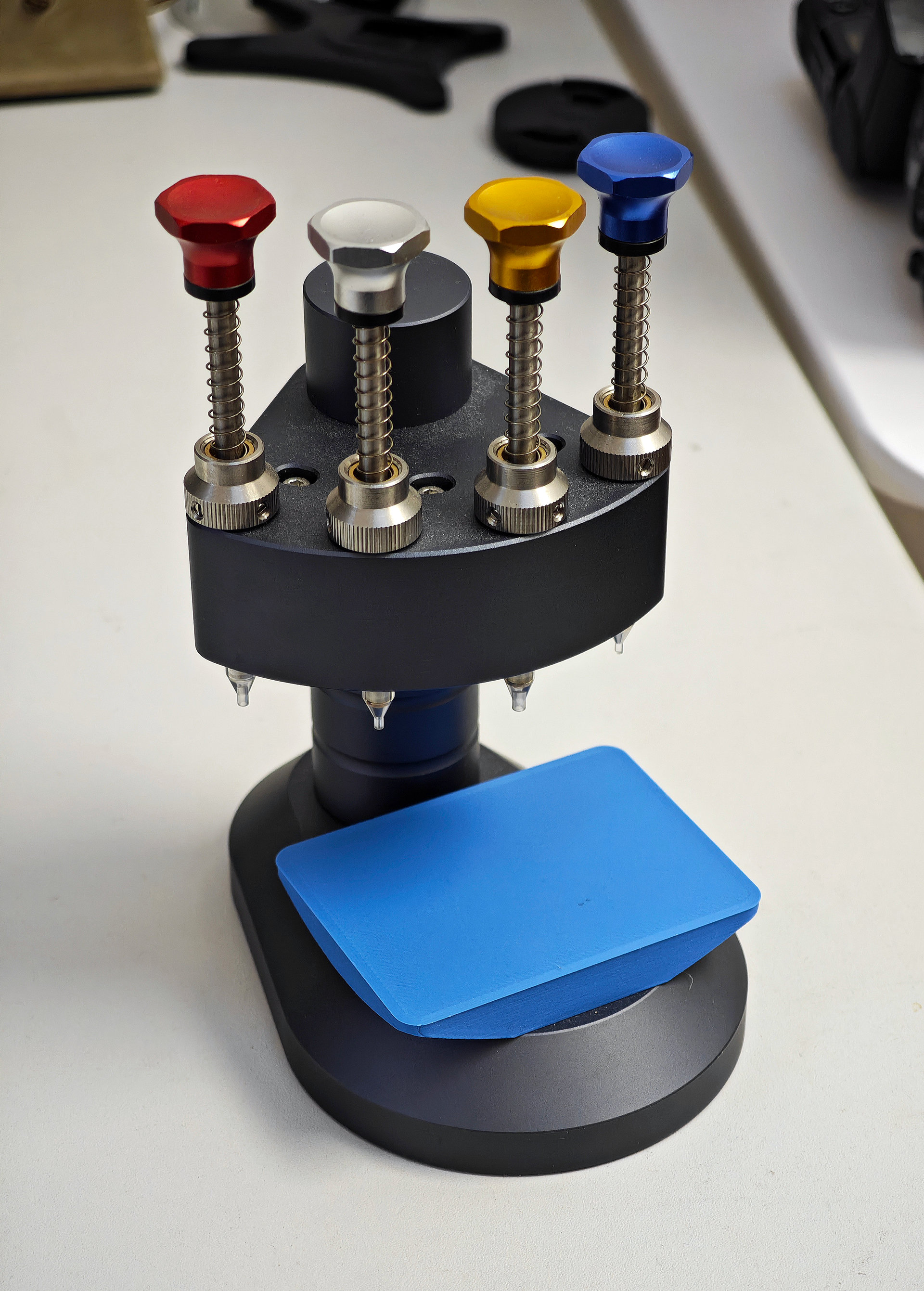
While many of these discovered options have been thoughtfully designed, they have not always worked for me in the way that I was hoping and I found myself reverting to the off-the-shelf solutions that I’ve become accustomed to. However, in browsing through the selection of cleverly imagined offerings, I found some tools that have absolutely made my life easier: for example, a platform base to fit my (at the time) newly acquired hand-setting press;
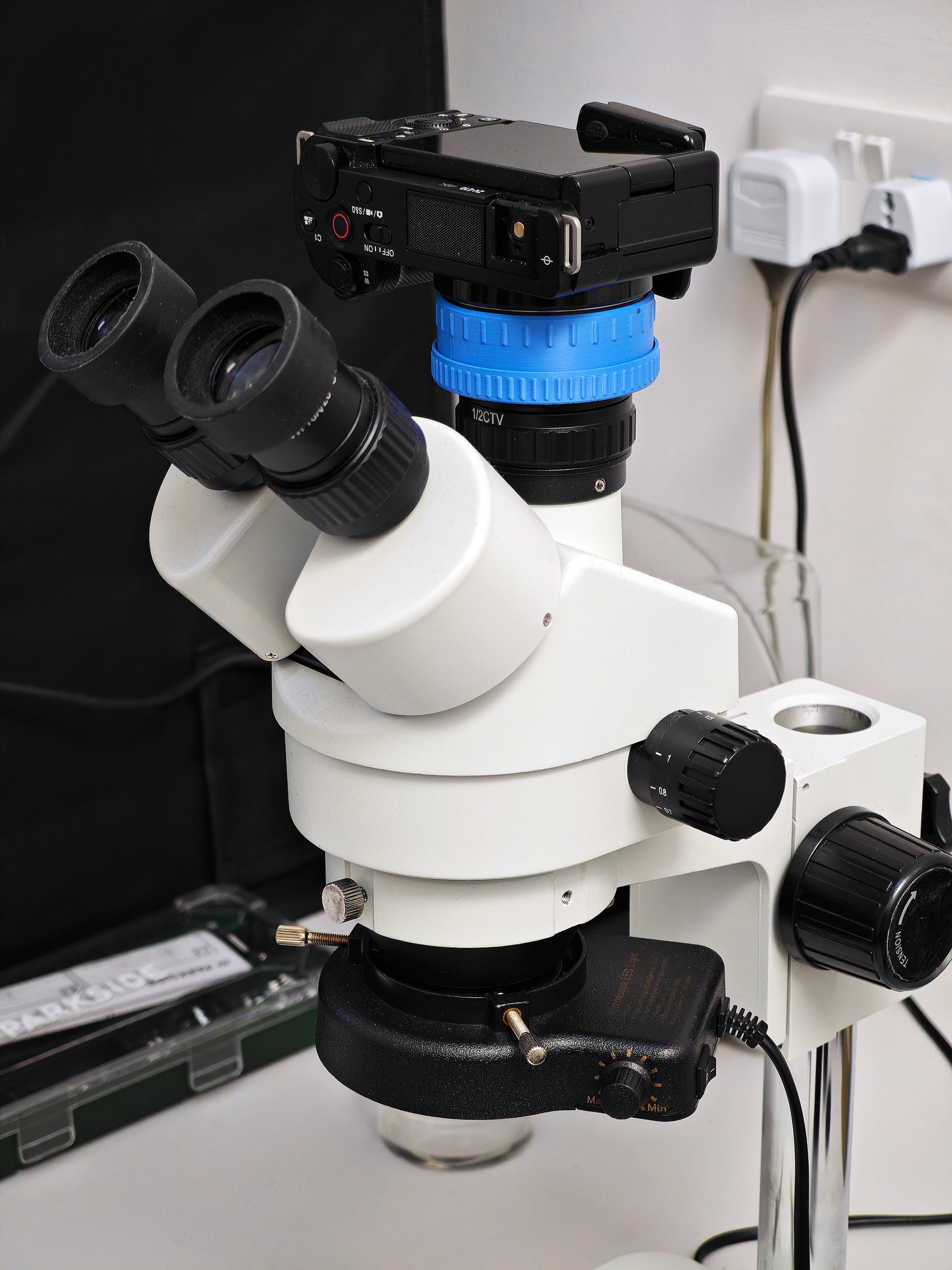
or, the adjustable mount adapter that allows me to fit my Sony mirrorless camera to the camera port of my stereo microscope.
Central to every project is the need to organise, store and sort the casing and movement parts as a watch is disassembled, and to support the movement safely during disassembly and reassembly. My objective in taking matters into my own hands was to realise solutions to these requirements that better fitted my workflow and, most importantly, to make my life easier. What follows is a description of the process from conception to design to production for two projects: the first, a set of interconnecting casing and movement parts trays and the second, a set of bespoke movement holders to fit most of the common vintage Seiko movement types and sizes.
1. Casing and movement parts trays
Years ago, I purchased a set of stackable parts trays from Cousins, and have used these quite happily since as my default solution to organising parts. However, the hard plastic is a dust magnet and the trays themselves occupy too large a footprint on my workbench.
I wanted something smaller with stackable trays dedicated to casing parts, mainspring, movement parts and a general-purpose lid that could also be used for miscellaneous purposes. The compartments within each layer would need to be sized to accommodate parts large and small and arranged to fit with the sequencing and organisational requirements of each project.
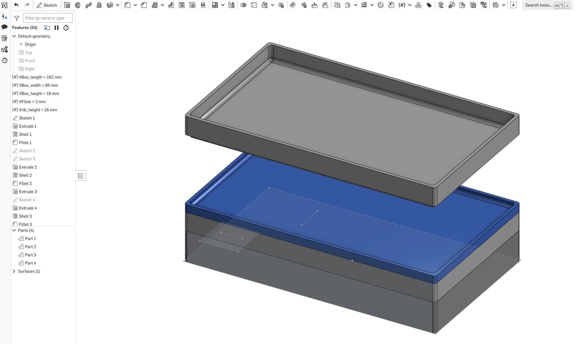
The first step was to find a computer-aided design software that I liked, could learn quickly and importantly, was either affordable, or preferably, free! I quickly homed in on Onshape which seemed to tick all the boxes, even the last one if you are happy for your creations to live in the public domain. The learning curve followed a gentle gradient, and after a couple of less ambitious excursions, one of which the design of a pair of VESA spacers for my son’s TV, I started working on some ideas for a set of stackable parts trays. After a couple of false starts, and adjustments to the dimensions, the final design came together. Here’s the overview with dimensions shown in the left-hand column. The height of each tray was defined by the intended contents, the deepest for casing parts, and the shallowest, the miscellaneous/lid.
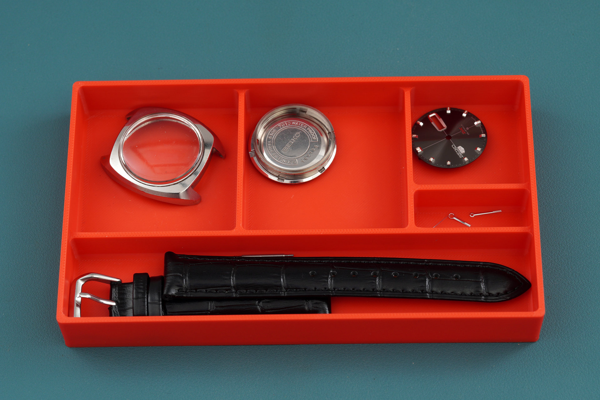
The interior compartment dimensions for the casing parts tray were set to accommodate the largest conceivable mid-case size with the height of the walls set low enough to provide ease-of-access to place and remove parts.

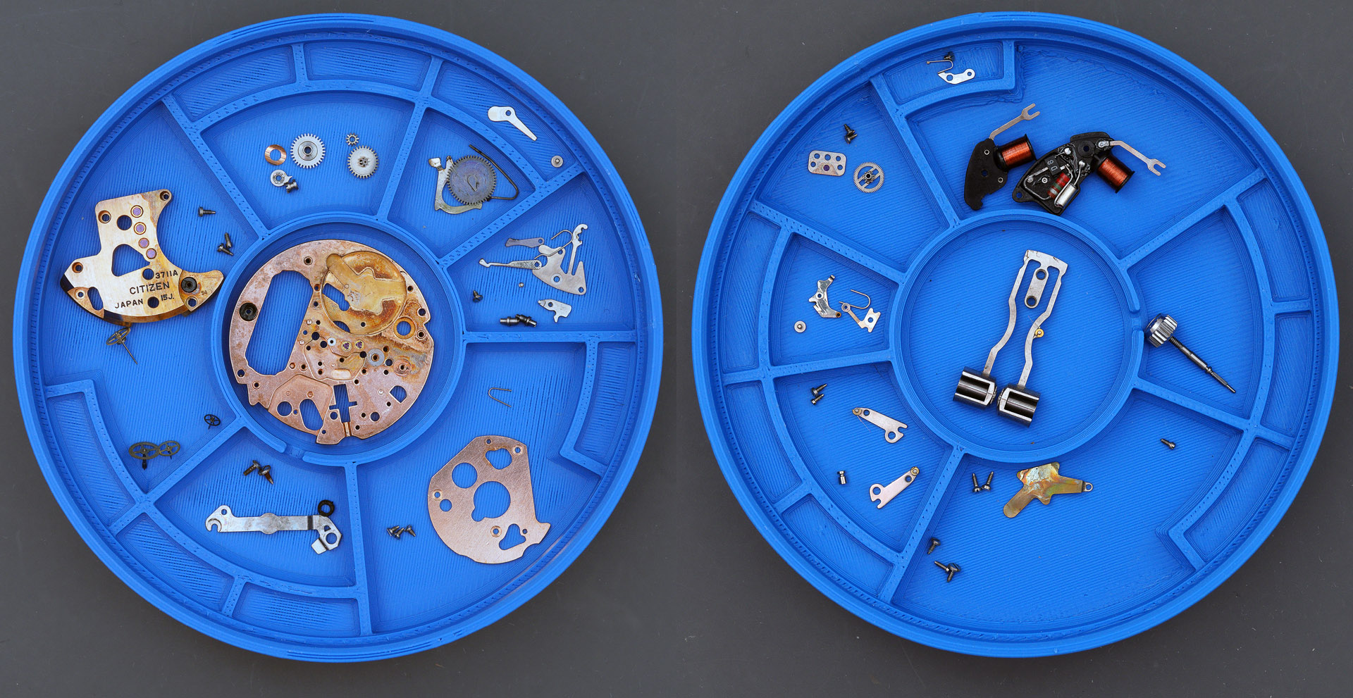
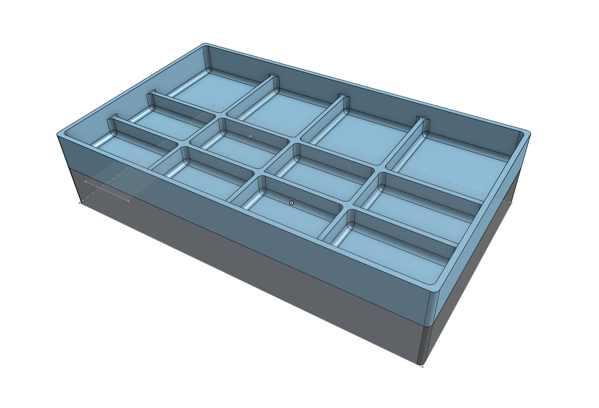
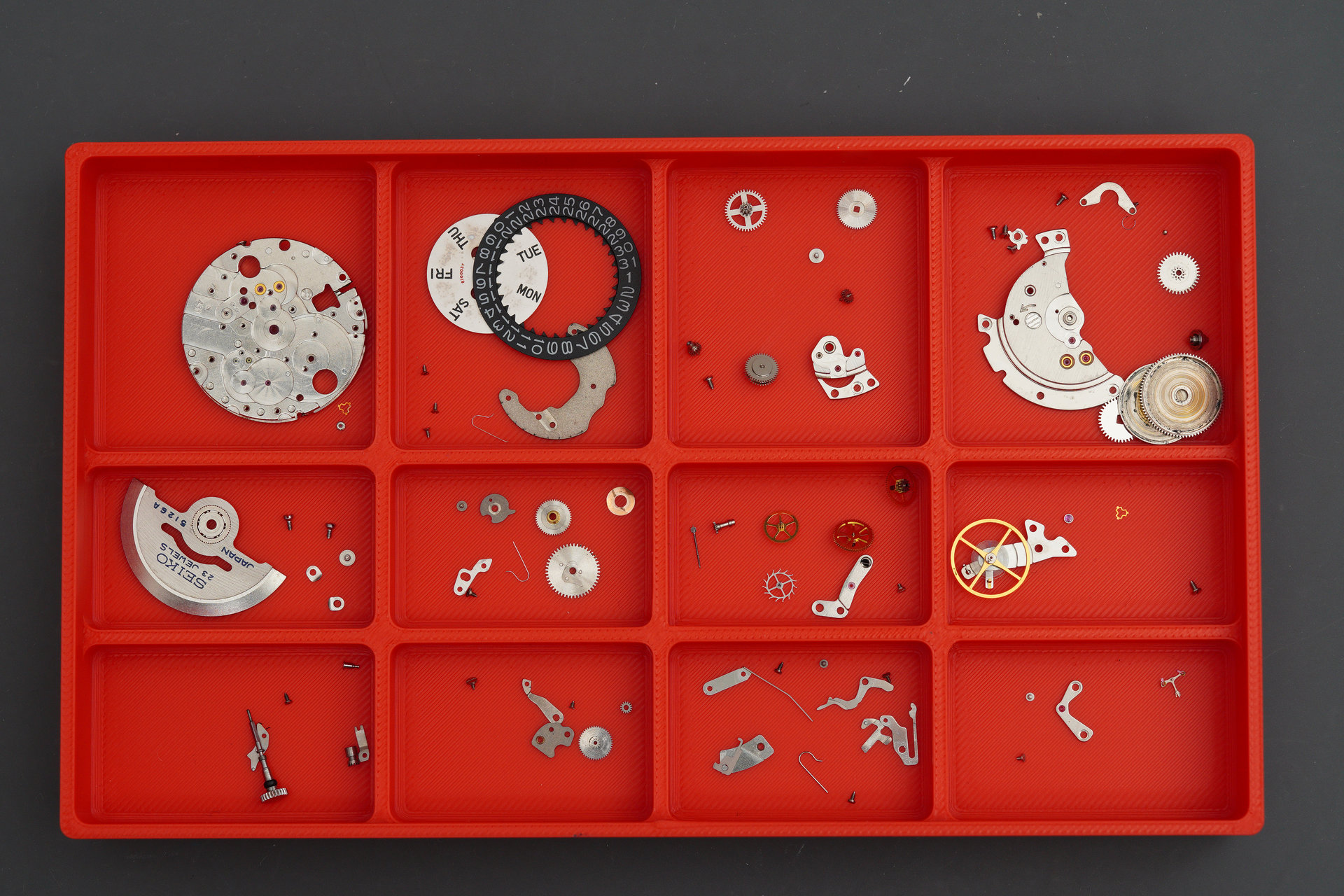
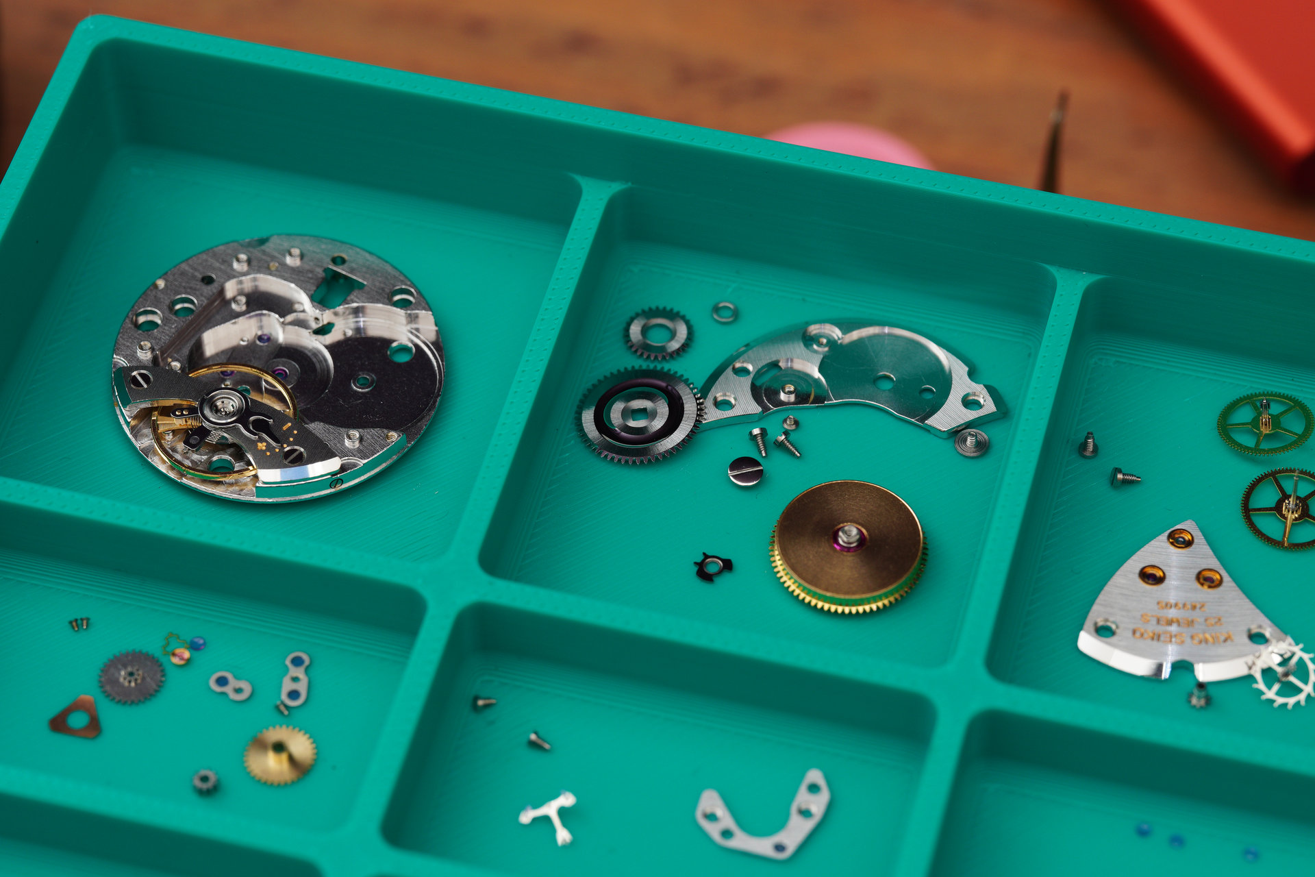
You’ll see later on what is supposed to go where (but I am sure you can figure that out at this stage). Similarly, the movement parts tray was sized according to the typical footprint of the different components but with a sufficiently useful number of separate compartments to help organise the parts.
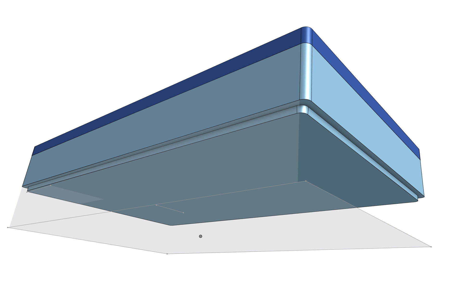
These being stackable trays, the base of each tray needed to be smaller than the aperture at the top and there needed to be enough clearance to ensure that the tray base did not interfere with the contents of the tray beneath. An important consideration in this detail was the ease with which the part would print because overhangs can and do cause problems.
Having settled on the design, the next step is to export the design as an .stl file which can then be imported by the 3D-printing software, which in my case is Bambu Studio.
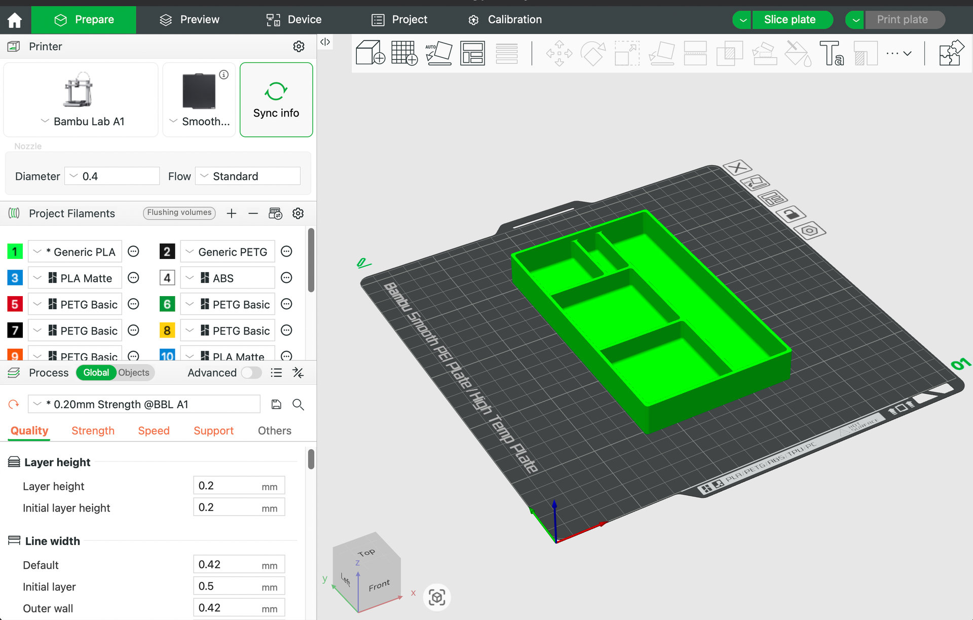
A lot of trial and error was required to get the quality of finish that I wanted and crucially that rendered the overhangs sufficiently cleanly to allow for a satisfactory fit between each tray. This involved a lot of trial and error in optimising the supports that prevent overhangs from drooping during the printing process. The supports need to provide a uniform platform that ensures a clean finish to the underside of the overhang but not so dense that removing the support afterwards presents a problem. Having imported the .stl file, adjusted the settings, and sliced the plate, we are ready to print.
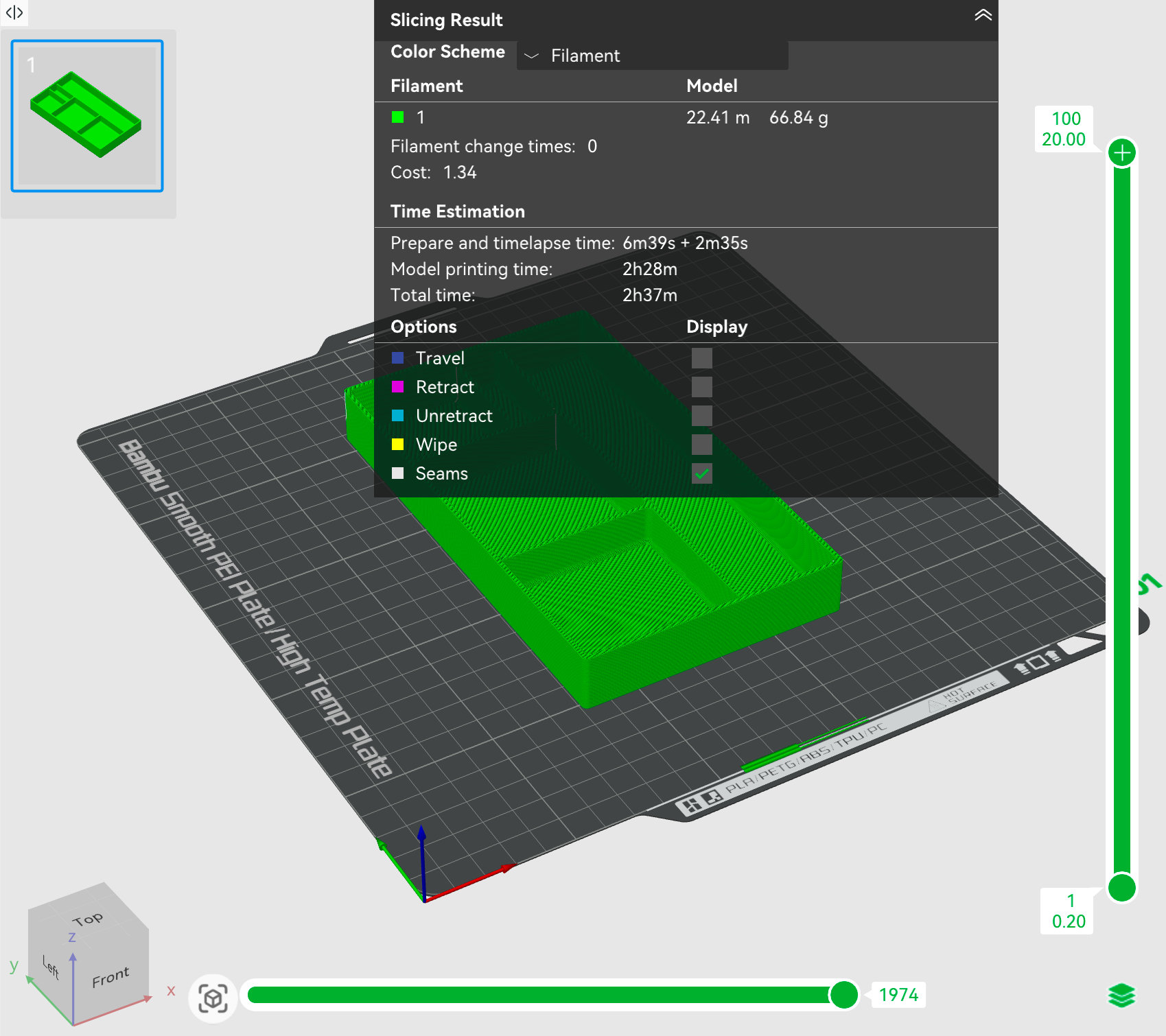
You can see from the image above that this print was going to take 2 hours 37 minutes in total and use 66.84g of filament. Here’s the result of that print, the part now incorporated happily into my workflow.
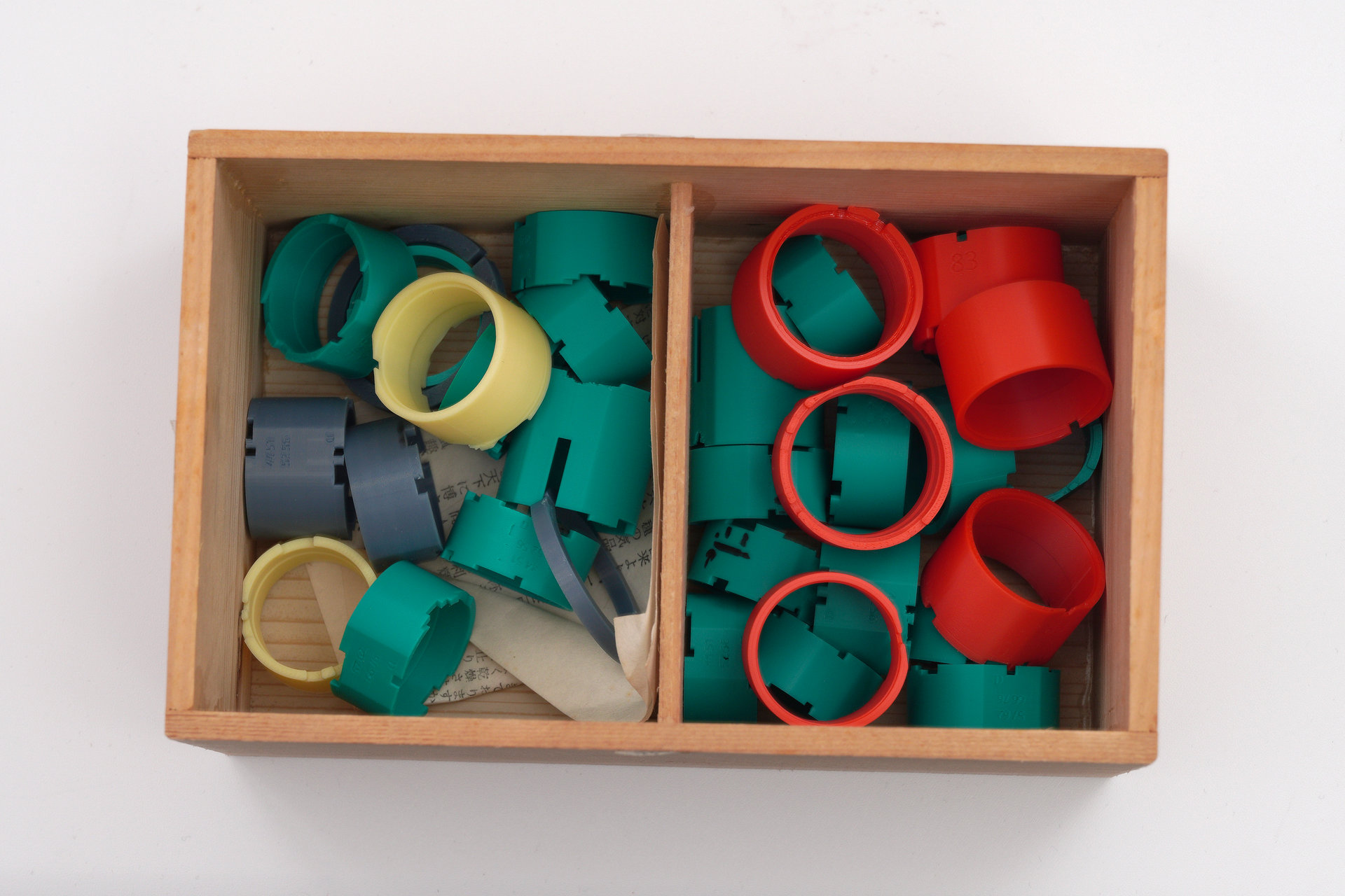
I repeated that process for each tray. Here’s the movement parts tray in action.
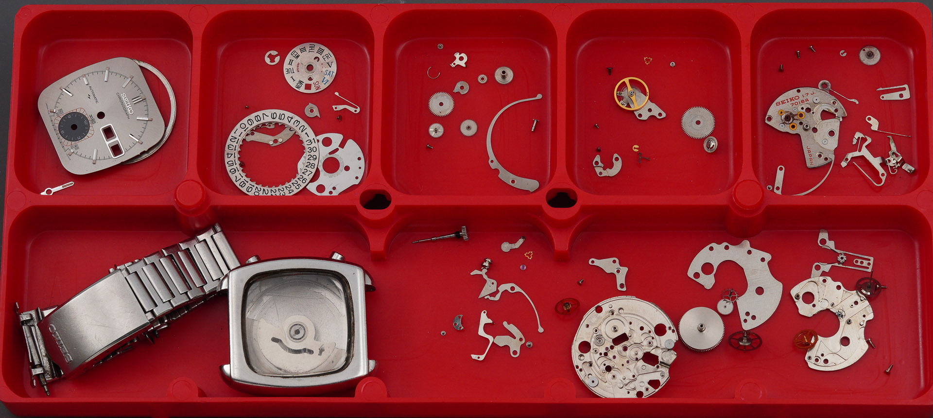
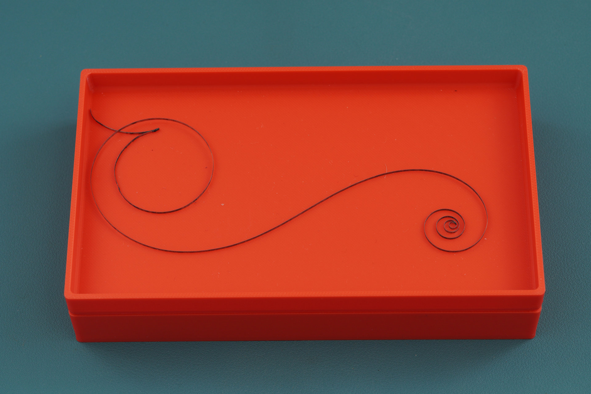
And here’s the tray dedicated to keeping the mainspring safe.
If red’s a bit garish, then how about sea green.
I’m really pleased with how these have turned out both in terms of the fit and finish but also how well suited they are to my way of working.
2. Movement holders
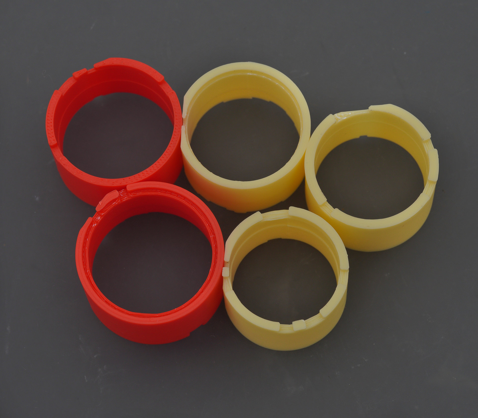
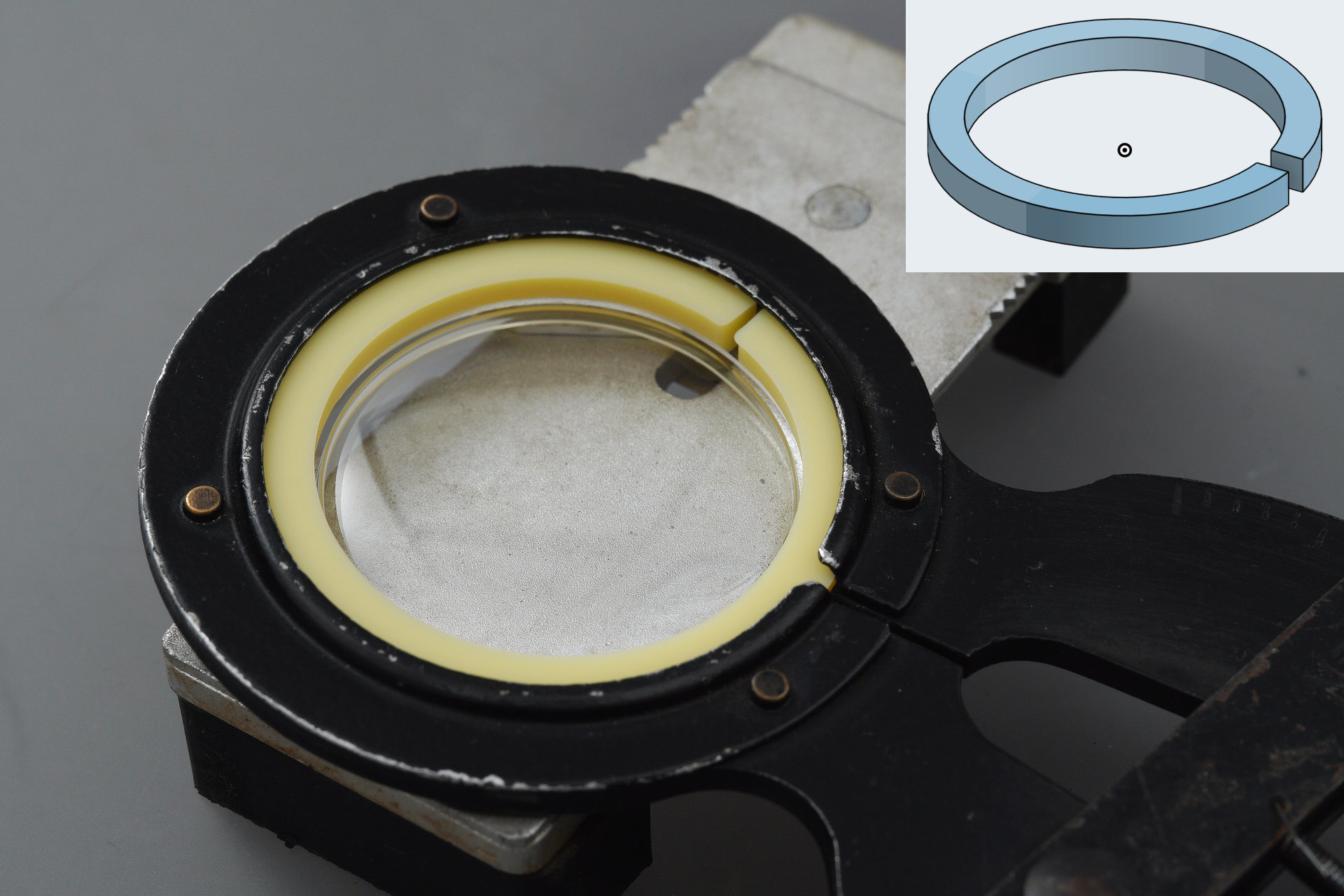
Some time ago, I reported on my success in having secured a set of 14 vintage Seiko movement holders spanning the smallest to largest Seiko calibres produced through the 1960s and into the early 1970s. I have enjoyed using these but I wanted to try my hand at producing my own equivalent set, one which perhaps might improve in some ways on Seiko’s designs. Having the origin tools to hand certainly helped me to sketch out the initial forays in producing my own designs. The process starts by drawing a cylinder of the external diameter and height required and from that point, extrusion is your friend, allowing you to hollow out the cylinder, defining wall thickness, create ridges for the movement to rest in, cut-outs for the stem and to provide access to dial screws. Here’s the finished rendering of the holder designed for the 57-, 62, 66- and 76-series movements, all of which having the same 27.6mm casing diameter.
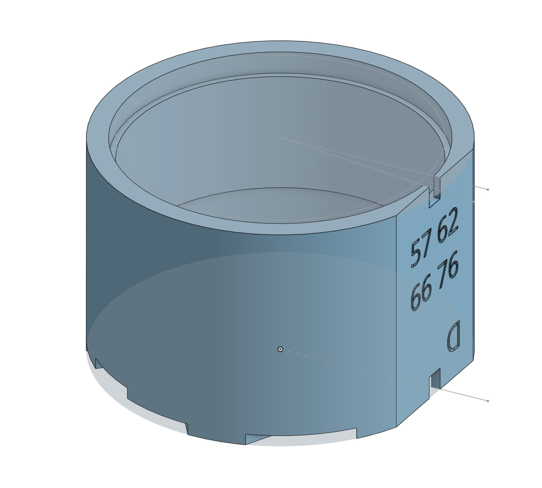
The internal dimensions of each end are sized to accommodate the movement sitting dial-side up or train-side up. I’ve incorporated a flat vertical surface on which I’ve added text to indicate the compatible calibres and to show which side is the dial side. The multitude of dial foot screw positions on this selection of calibres has made for a rather complex profiling on the dial side.
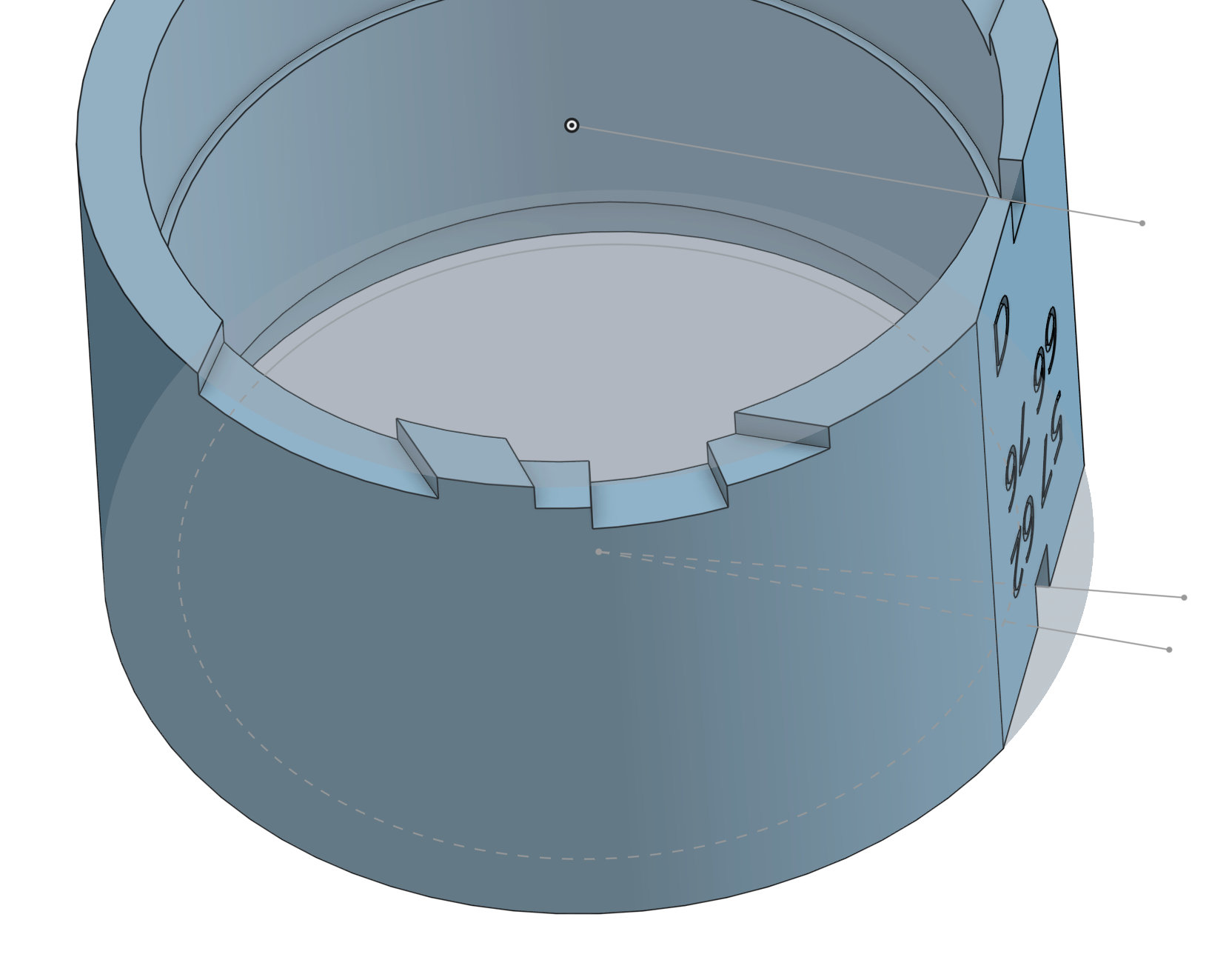
The curious angles of some of the cutouts is to accommodate the tangental position of the dial foot screws in the 66-series movements, providing clearance for a screwdriver.
All of the details were defined and then refined by making prototype dummy prints, and using a selection of spare movement main plates as references for internal dimensions on the dial and train wheel sides of the holder and the position of cutouts for access to dial foot screws. This necessarily involved a degree of wastage!
I repeated this process for five different calibre sizes covering diameters ranging from 25.6mm (37-, 44-, 51-, 52- , 56-series) to 31.2 mm (4005 and 4006).
Here are some of them in action.

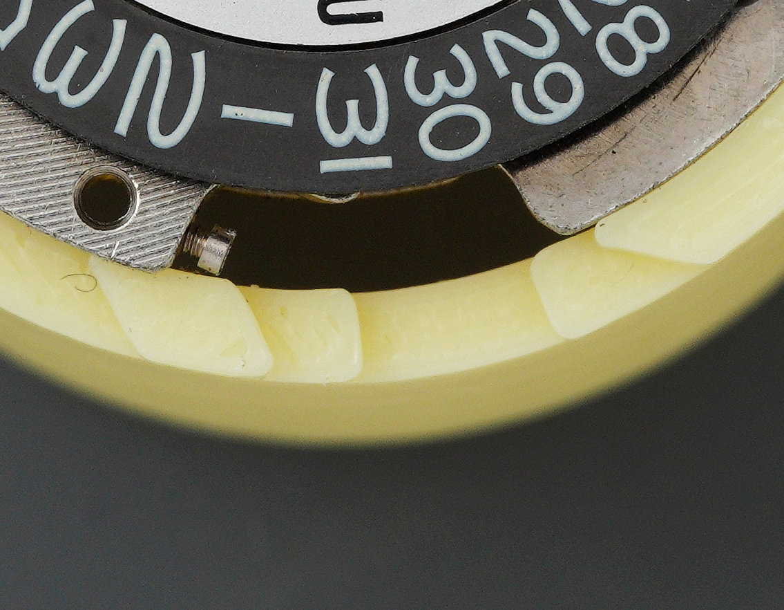
Well, actually, those are all of the smallest in action, supporting early King Seiko (off-diagonal) and 5126 (diagonal). One of the most useful features of these holders is that they support the movement with the dial fitted, allowing easy access to the dial feet screws, wherever they may be located (with the honourable recent exception of an Elnix movement, also 25.6mm, but whose dial feet screws are fixed eccentric screws located on the train-side plane of the main plate). It’s been rewarding and fun to burrow down this rabbit hole and has resulted in tools that I am using all the time. I will continue to refine the designs of the holders as their use reveals minor shortcomings and, as ideas occur, to put my printer to good use as other applications present themselves.

There are lots of well thought tools for 3D printers. One interesting tool I’ve seen is a 6139-600x Press Die for Bezel Alignmen. Its functionality is explained here, you might want to have a look at it: https://wristsushi.proboards.com/post/301777/thread
I quite agree! One other set of tools I’d be interested in either finding or making are case back openers. No risk of damage from slippages!
That’s my press die! Glad to see it being appreciated.
Wonderful write-up, as usual, Martin. Congratulations on taking on a new hobby and learning new skills!
As a mechanical engineer, watchsmith, and owner of a 3D printer, I can confirm that no other tool enables such a degree of creativity and problem solving as a 3D printer and CAD software.
One could argue that methods of subtractive manufacturing, such as turning or machining, allow for the manufacturing of more robust tools/parts. But once the constraints related to FDM printing with plastics are understood, one can easily make tools robust enough for almost any day-to-day application.
Thanks Marcus. One of the other benefits is you can make cost-effective prototypes that might then serve as the basis of a machined part. I don’t know if you watch the Retropower uncut YouTube videos but they do that all the time.
Would you be able to share the stl files so we can print them?
Hi Scott, I’m thinking about how I might do that once I’ve worked through some refinements based on my experiences working with the various tools. That may take a little time as I’m elbows-deep in a number of projects.
All the best
Martin