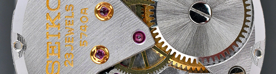
In 1968, Seiko established a new project team whose blank-sheet brief was to produce a shock-resistant, corrosion proof, anti-magnetic watch designed from the outset for saturation diving. In 1975, after seven years of research and development, the first Seiko Professional 600 m diver’s watch emerged and the Tuna dynasty was born.
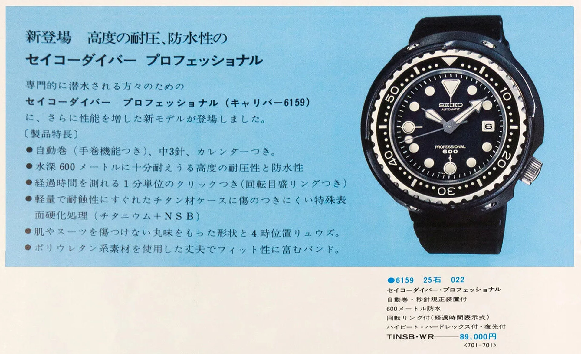
That first watch was fitted with the high-beat automatic 6159 movement housed in a top-loading monocoque case constructed from titanium, and featuring an L-shaped crystal gasket and a screw-down crystal retaining ring that rendered the case impermeable to helium gas. Its distinctive appearance owed much to its separate shroud that screwed onto the case, providing additional protection to the bezel and crown.
At 50mm diameter, this was purpose-built tool watch designed for function rather than everyday convenience. The stubby cylindrical case shape inspired the adoption of the nickname Tuna, spawning a long line of models that sustains (by the skin of its teeth at the time of writing) to the present day.
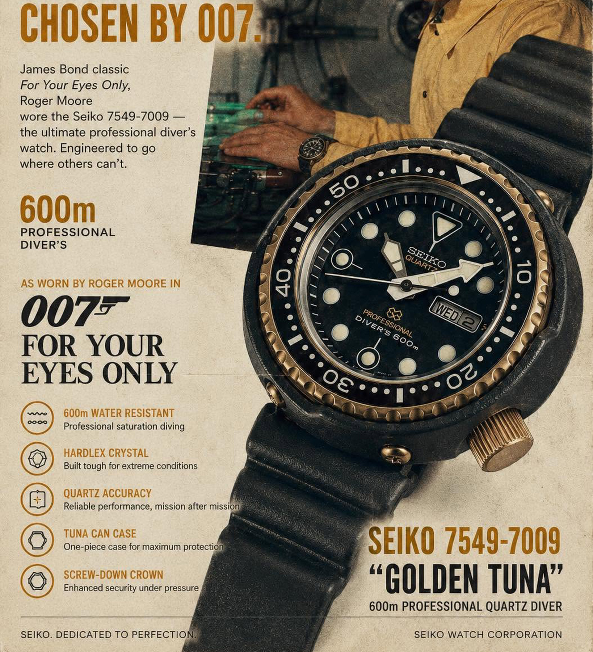
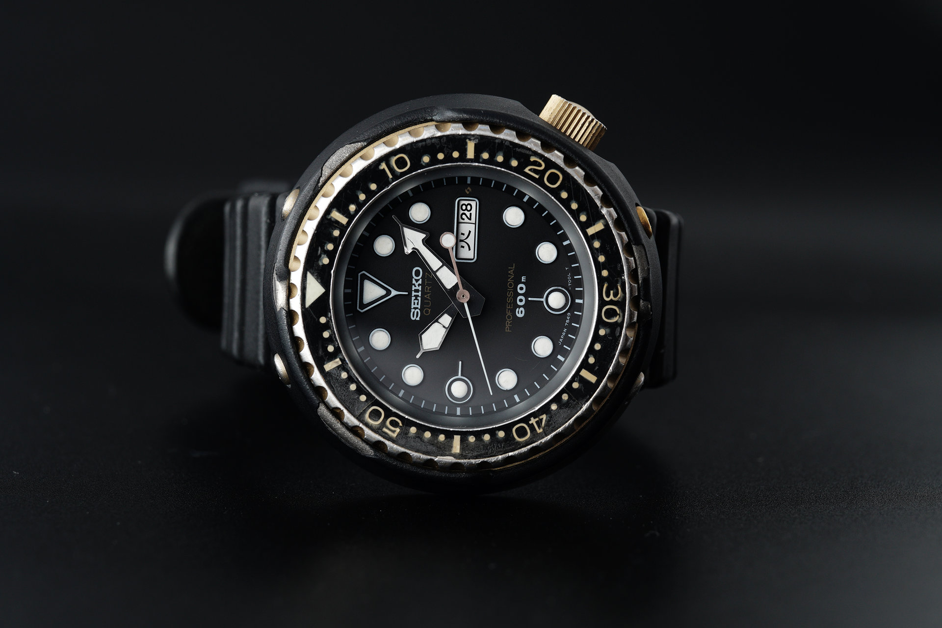
The high-beat movement fitted to those first watches was subsequently replaced in 1978 with the five jewel 7549A quartz movement in the celebrated 7549-7009 Golden Tuna, named for its distinctive gold-coloured titanium nitride-coated titanium case. It is an example of this later model, dating from August 1978, that forms the basis of the current entry.
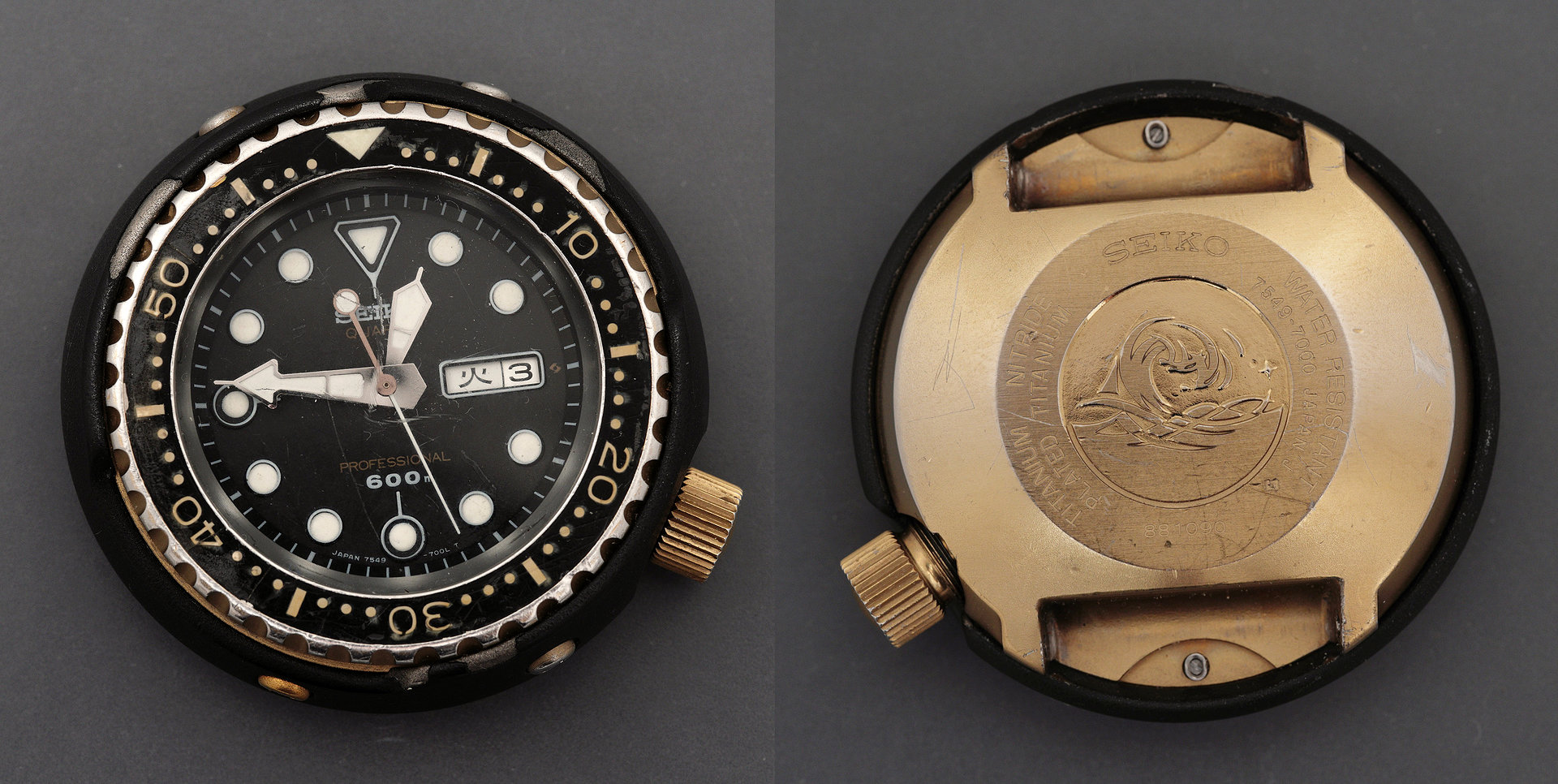
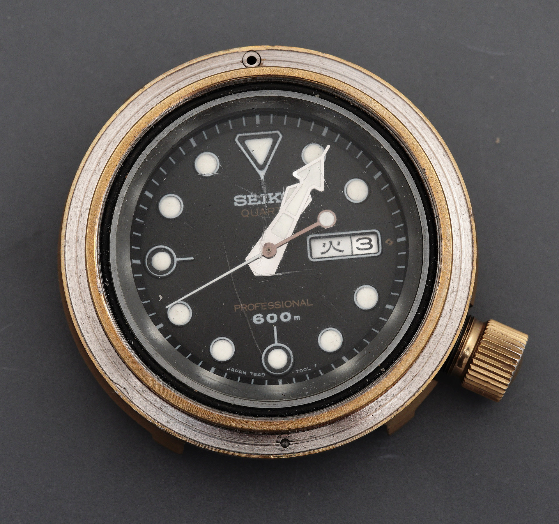
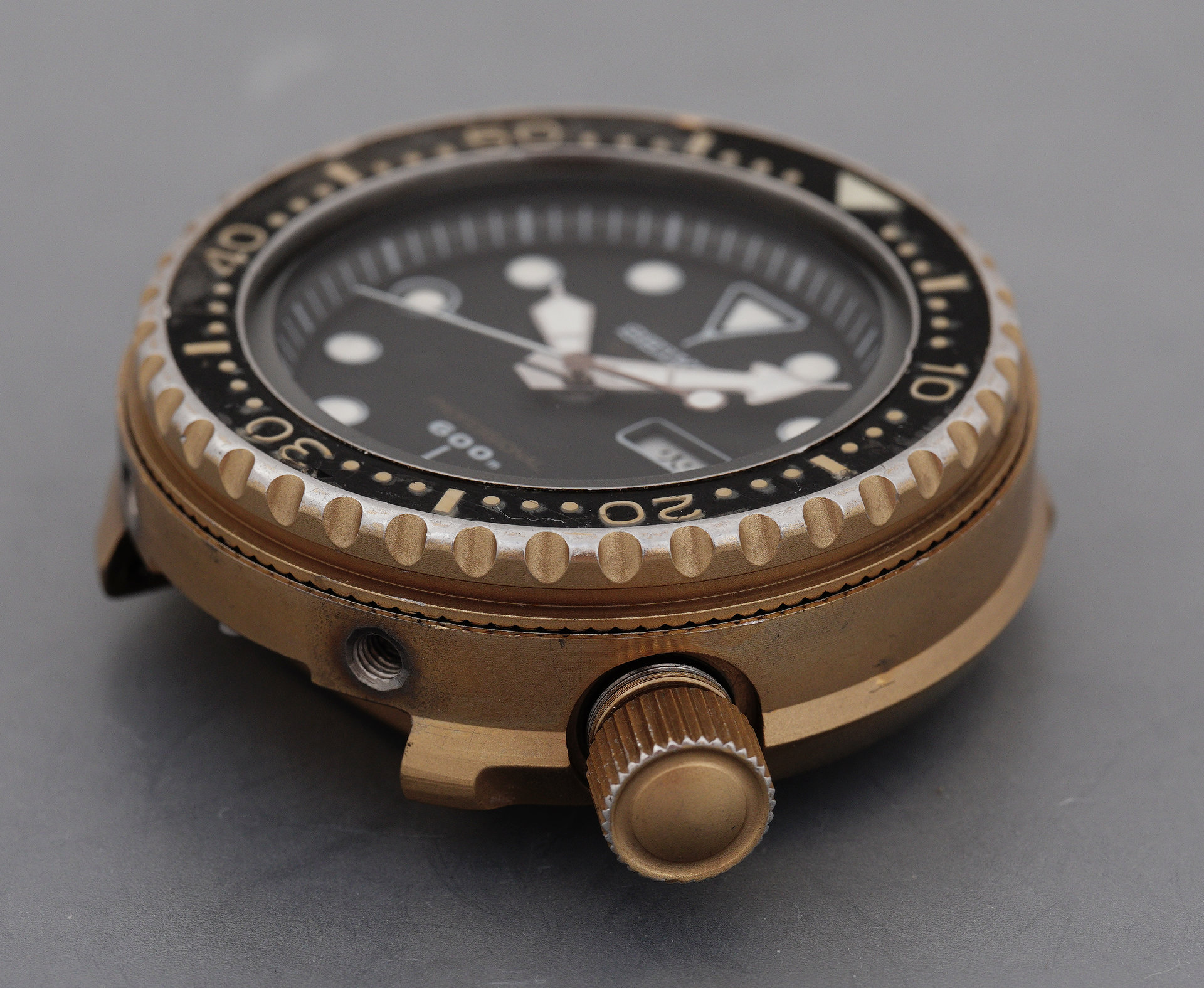
As may be clear from the opening pair of photos, this looks like a watch that has either been well-used for its intended purpose as a diver’s watch or has been worn and treated as a tool watch for which day-to-day impacts, clatters and wear are an occupational hazard. In spite of this, or indeed as a consequence, this is a watch brimming with character and attitude and it deserves a sympathetic restoration to restore its function while preserving the external marks of a life well-lived.
Continuing our external appraisal and we can take in the condition of the shroud and its retaining screws.
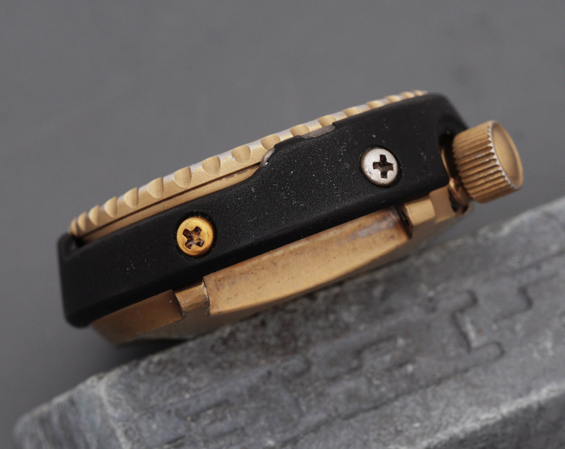
The black ceramic coating is mostly intact apart from a number of areas around its most vulnerable leading edge where narrow strips are missing. Only one of the four titanium nitride-coated shroud screws retains its original characteristic gold colour: the most likely explanation is that three of the four original screws had been misplaced during one of the numerous historic battery changes and that lesser replacements were then used, presumably those intended for the lesser 7549-7010 (see here).
Removing the shroud reveals its dual purpose: not only does it protect the body of the mid-case from impact, but it also secures the turning bezel which, once free from the embrace of the shroud, lifts away without resistance. This is a smart design choice aimed at avoiding wear that would otherwise accrue from repeated bezel removal/refit cycles required at every battery replacement in a watch where entry is gained from the top rather than via a conventional screw-down case back.
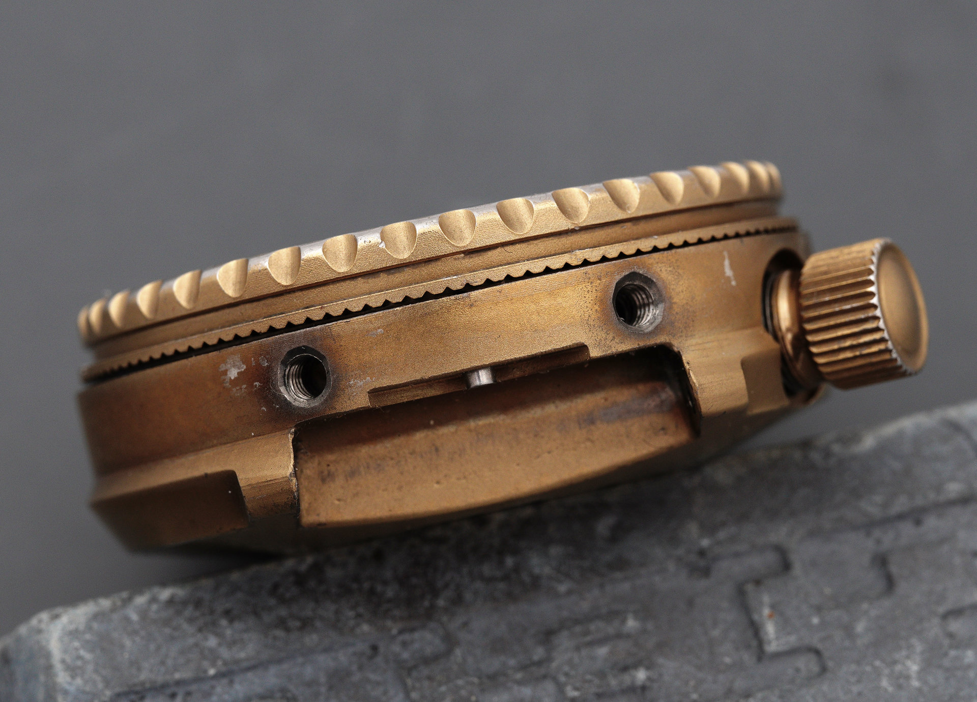
Notice how the bezel lifts naturally from the left side without the containment of the shroud. Consequently, in contrast to almost every other Seiko diver’s watch, little effort is required to prise the bezel up and away from the case.
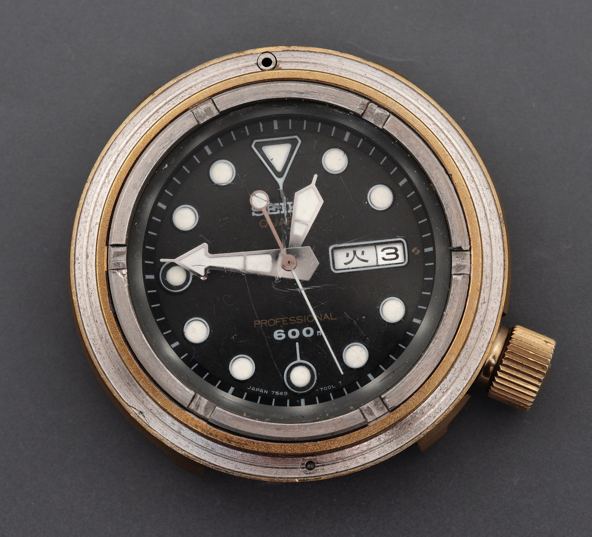
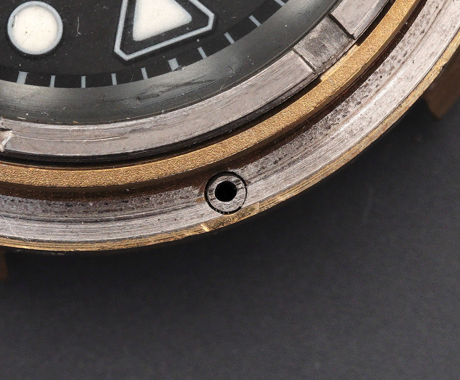
The imperviousness to helium, not to mention water, to a depth of 600m is aided by the combination of an L-shaped crystal gasket with a screw-down crystal retaining ring. The castellation of its profile is the result of the slots provided for the teeth of a removal tool. Two observations should be noted at this point: firstly, one of the two sprung-loaded bezel click ball bearings is missing (the one immediately above the 12 o’clock marker).
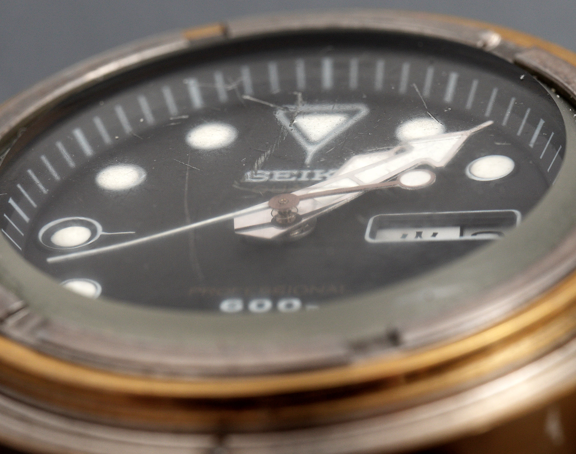
Secondly, and somewhat curiously, the seconds hand has been bent downwards at both ends, with the result that it is fouling the minute hand, and therefore impeding the operation of the movement. Whether as a result of that or another incident or a flat battery, the movement was not running on receipt. We shall discover in due course the reason for that.
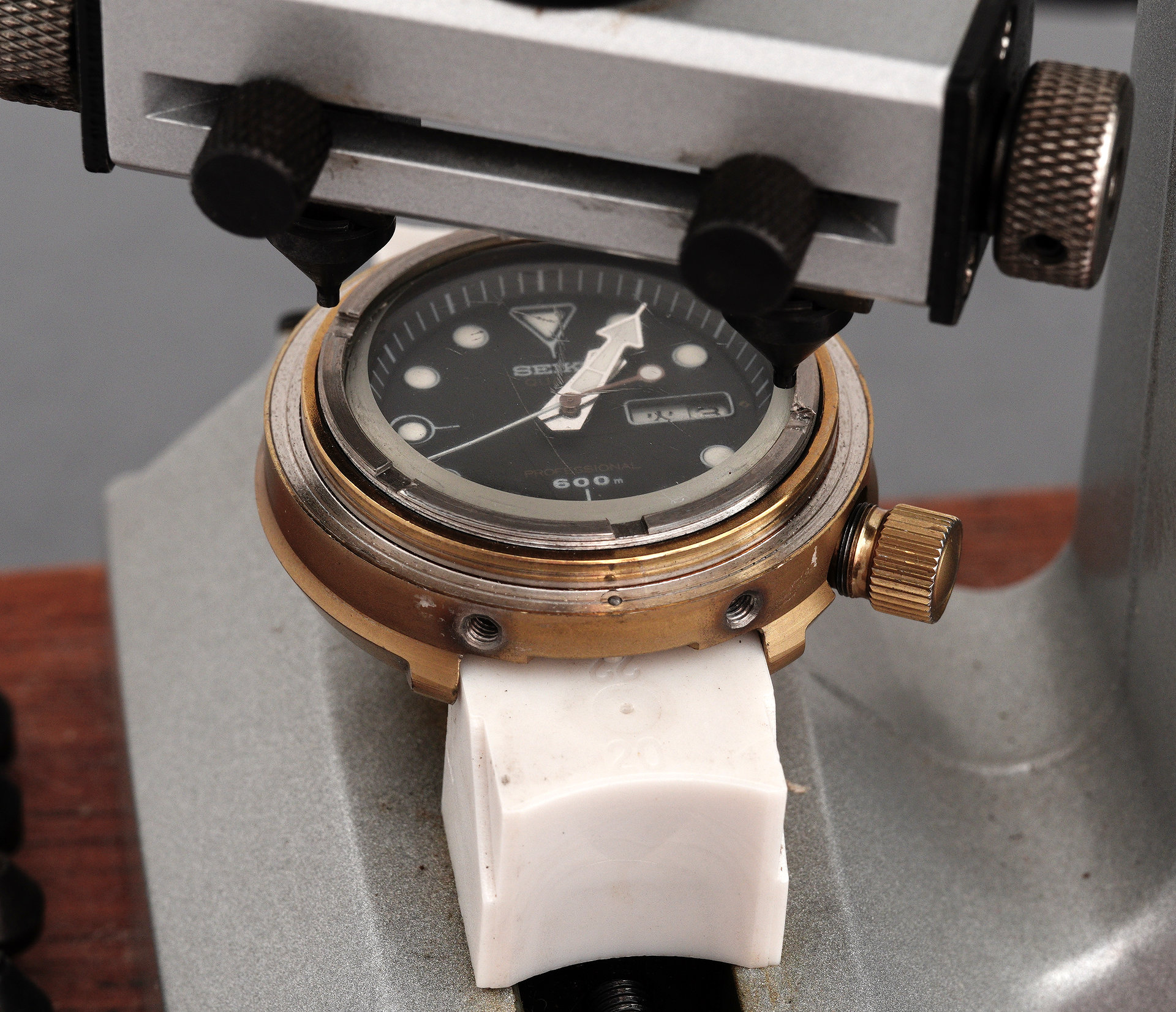
The next step is to remove the crystal retaining ring and that is an operation best not performed using a hand tool.
I seem to be documenting this as a step-by-step account, and so continuing in that spirit, here’s the watch head now free of the retaining ring, the vertical arm of the L-shaped crystal gasket visible as is the nylon glass fixing ring gasket that sits around the stepped-edge of the crystal.
The crystal can be levered out at this point. Note the stepped profile.
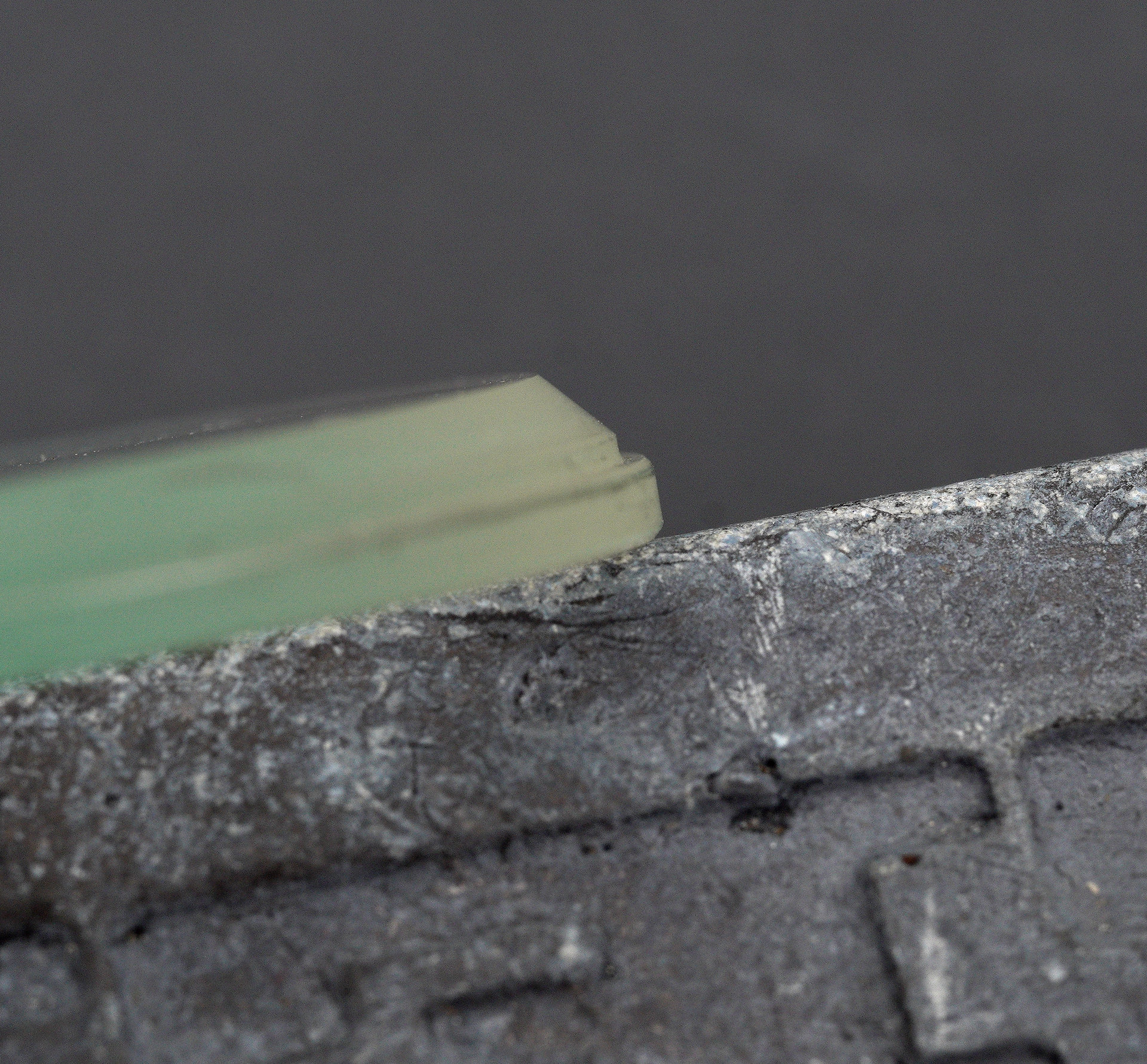
As we continue to peel away the layers, we can start to appreciate that the routine of replacing the battery every three years is anything but routine. The removal of the crystal also provides a view of the horizontal part of the crystal gasket (not to mention how dirty it is!).
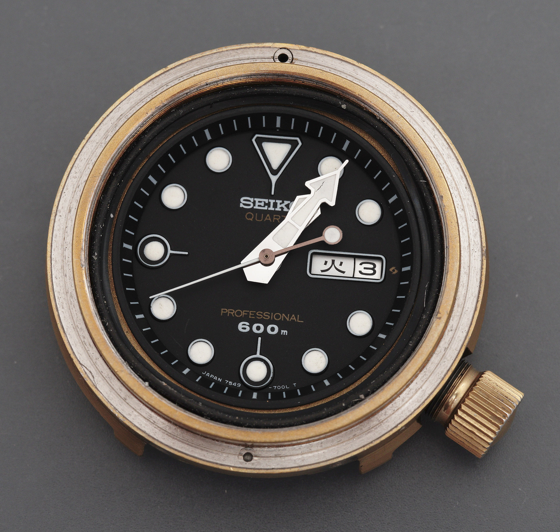
Removing the crystal gasket takes us one step further in but still two steps away from being able to access the setting lever.
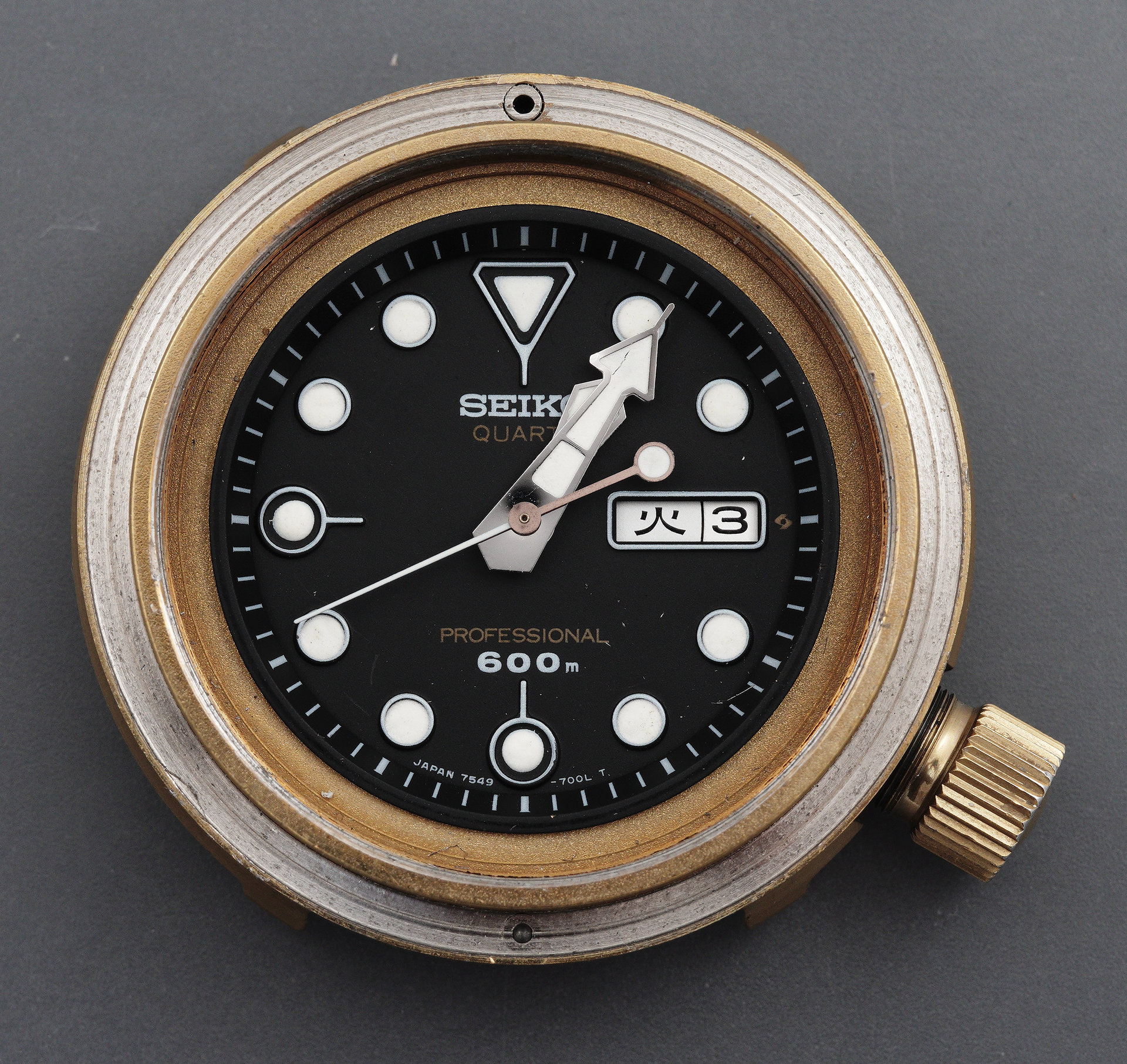
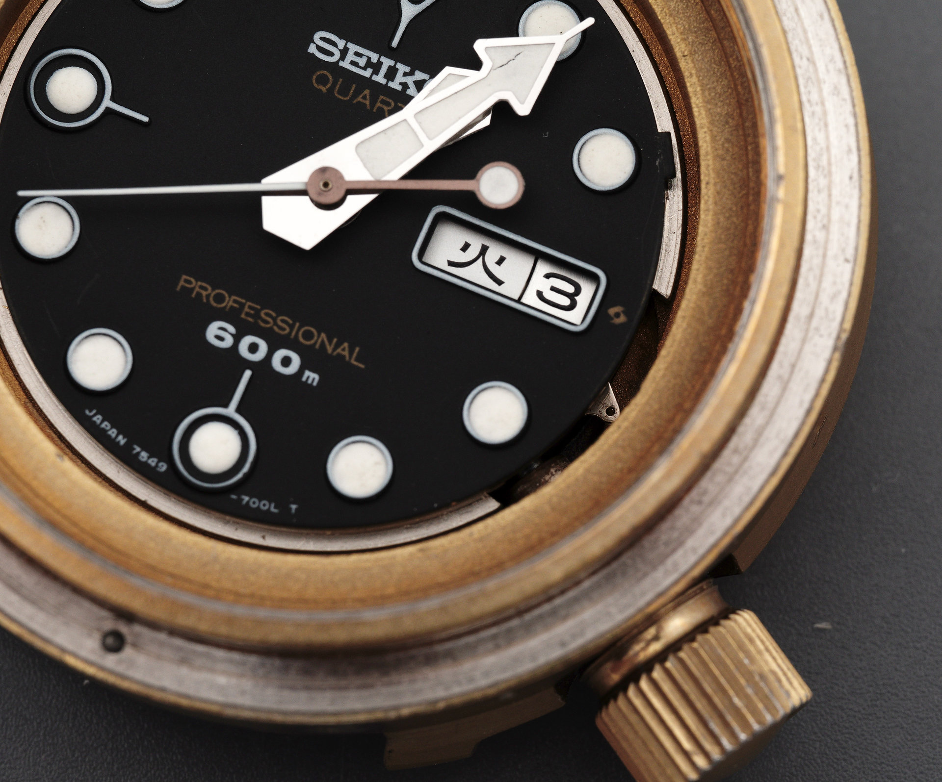
If we approach a little closer, we get a clearer view of the damage to the end of the hour hand: the lume is cracked and one of the outer apexes of the arrow-head end bent downwards. It doesn’t require much in the way of detective skills to conclude that this damage and that inflicted upon the seconds hand can only have happened during a previous battery change.
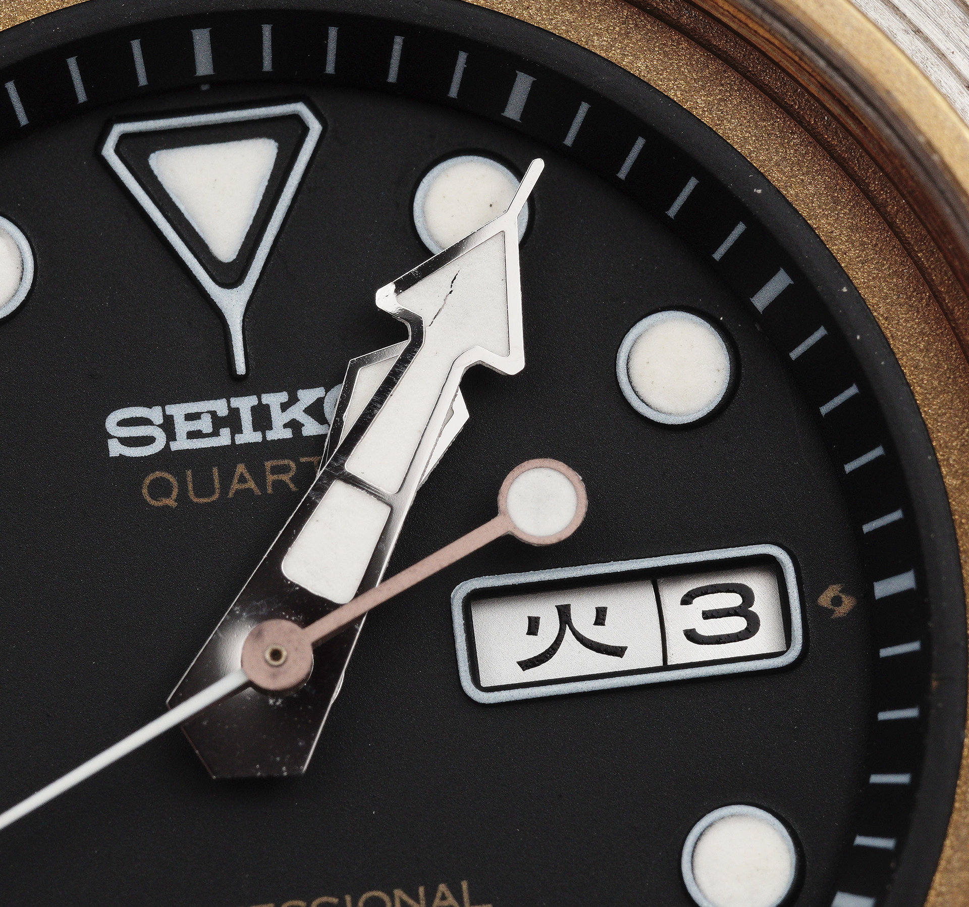
The hefty chapter ring is the next on our long list of components requiring extraction.
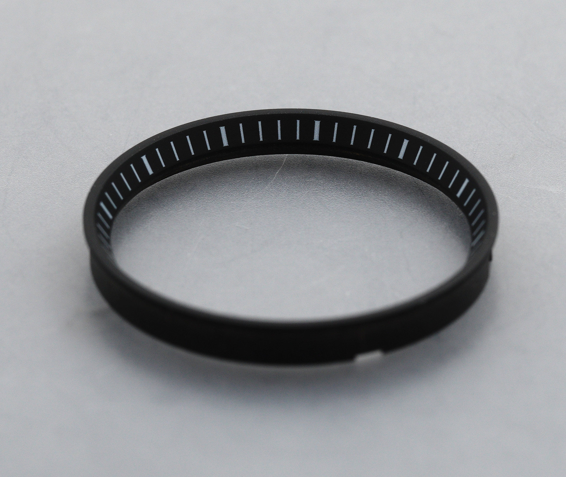
You might reasonably think that with that out of the way, we might have an unobstructed view of the edge of the movement but no, instead we are met by a rubber gasket sitting around the edge of the dial which Seiko refers to as the movement fixing gasket in the technical manual. The purpose of this gasket therefore, would seem to be to provide a measure of shock resistance rather than as a further barrier to water ingress.
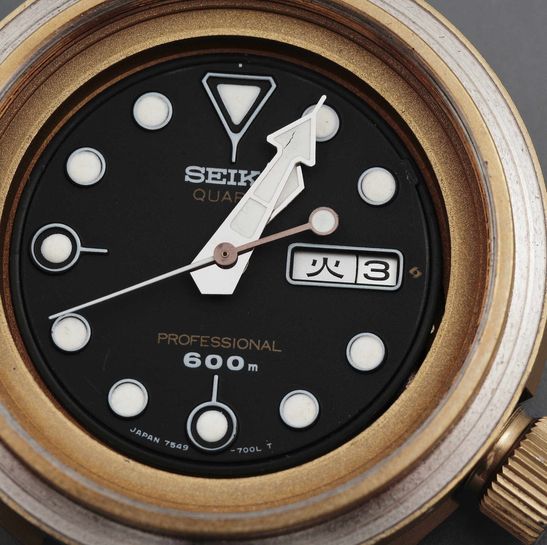
Finally, with that last remaining gasket removed, we can access the setting lever.
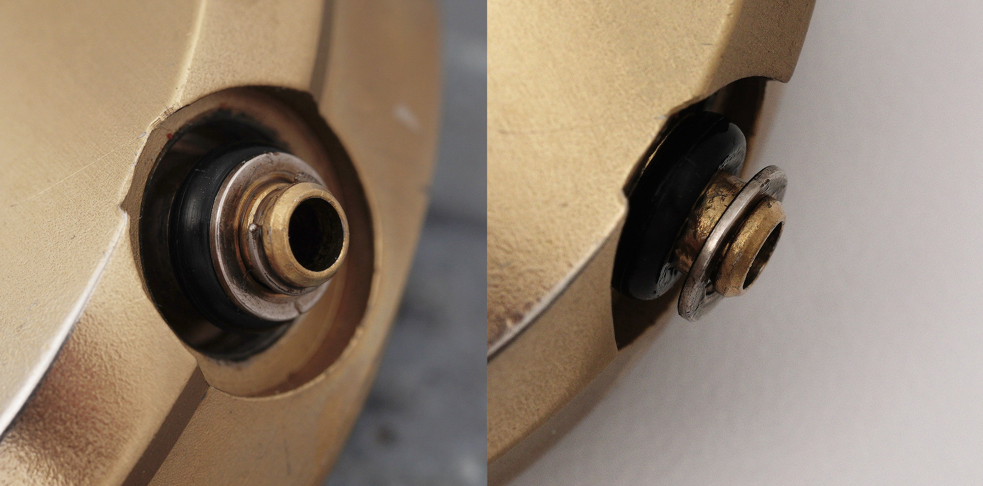
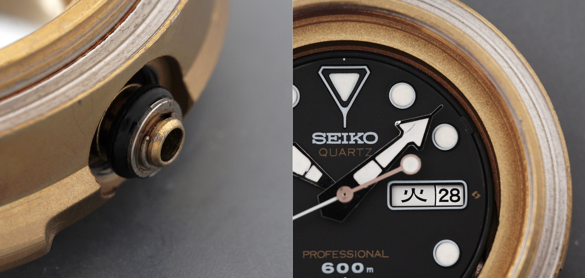
Pressing the lever and pulling the unscrewed crown, releases the crown and stem, revealing a crown design similar in some respects to that of the contemporary 150 m 7548 diver’s watches, but where the thread sits on the outside of the crown here rather than the inside in the 7548.
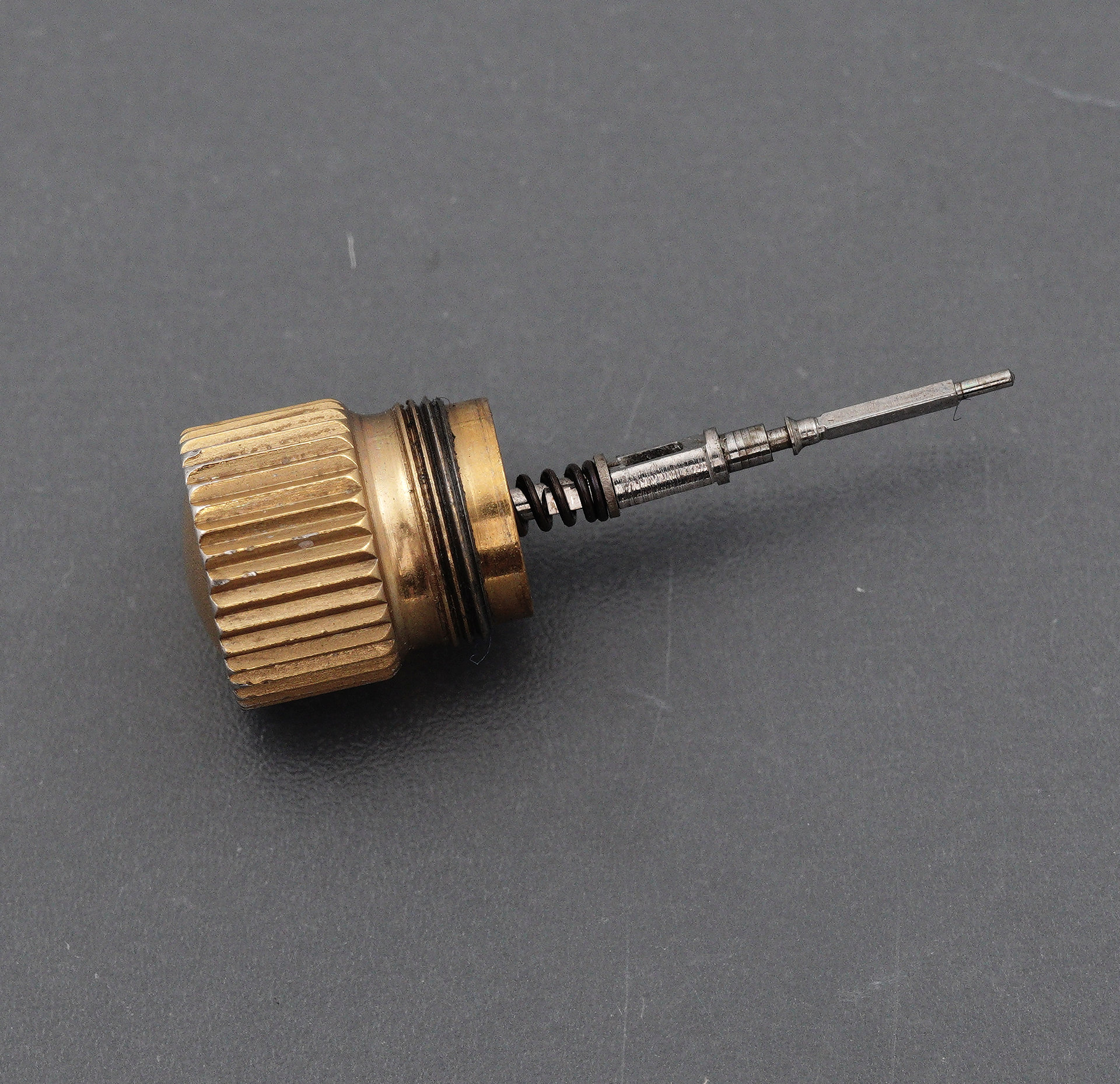
The outer threads imply that the reciprocal threading on the case is not on the crown tube but machined into the interior wall of the tube hollow in the case. The water resistance is provided by an extremely girthsome rubber o-ring gasket sitting around the crown tube and held in position with a steel washer and secured by a c-clip.
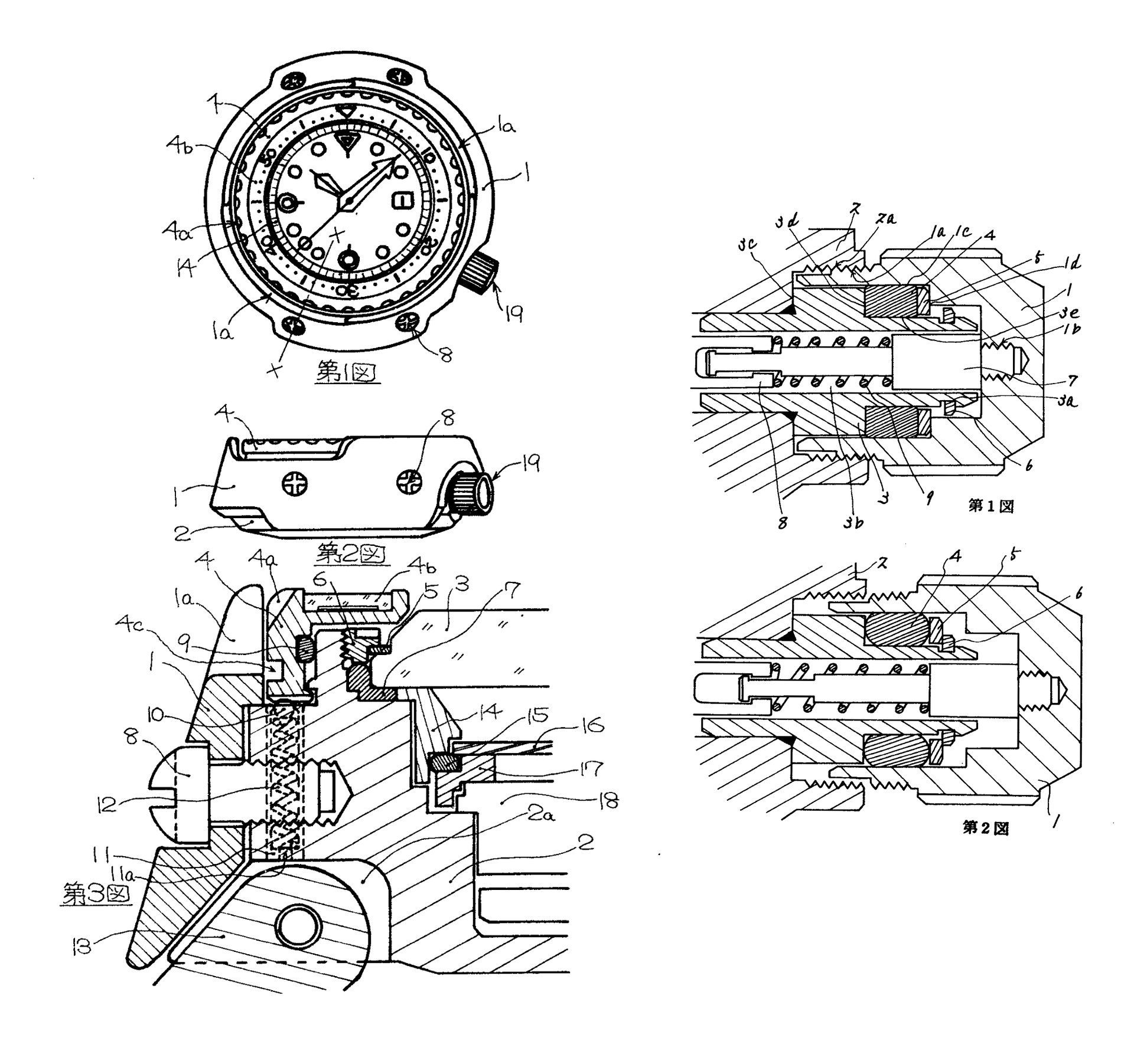
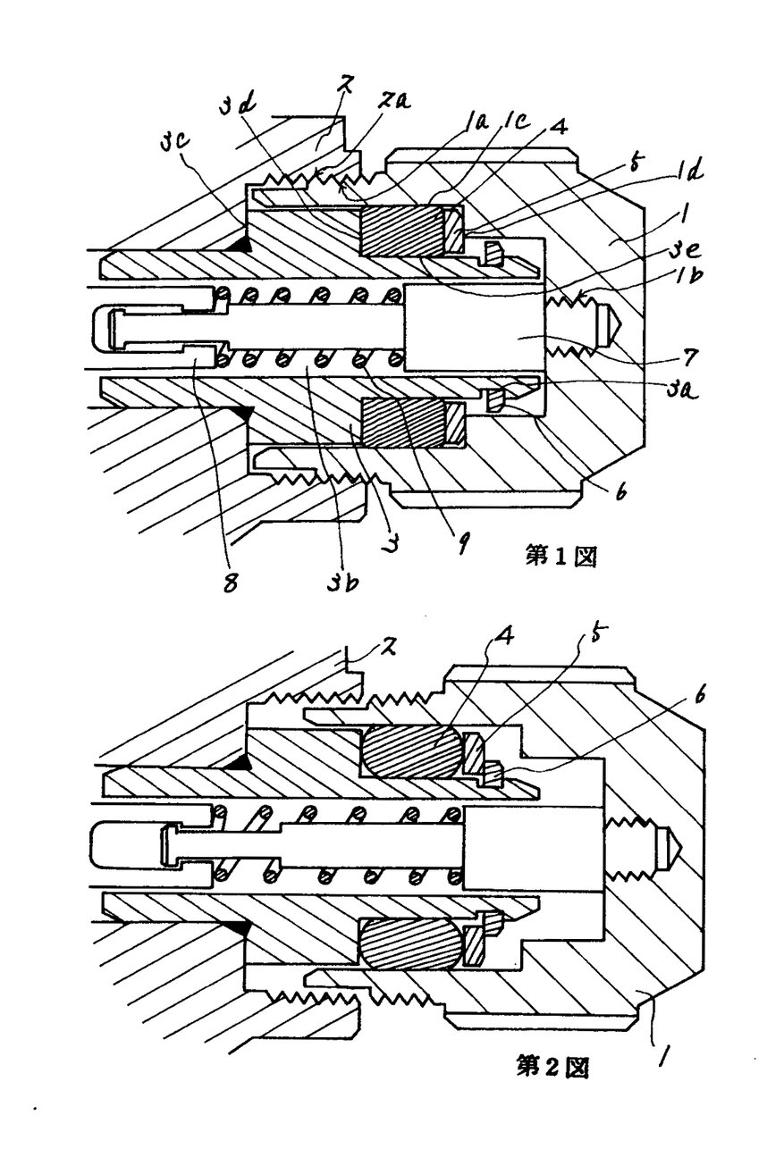
Returning to the cross-section drawings of the crown from the patent document, you can see how the various elements work together to compress the gasket when the crown is screwed down, the gasket completely filling the space between the inner wall of the crown and the outer wall of the tube (upper sketch in the figure below).
The movement is now free, requiring inversion of the case to liberate, leaving an empty case barring the imprinted marks documenting the numerous previous battery changes on its shiny antimagnetic shield.
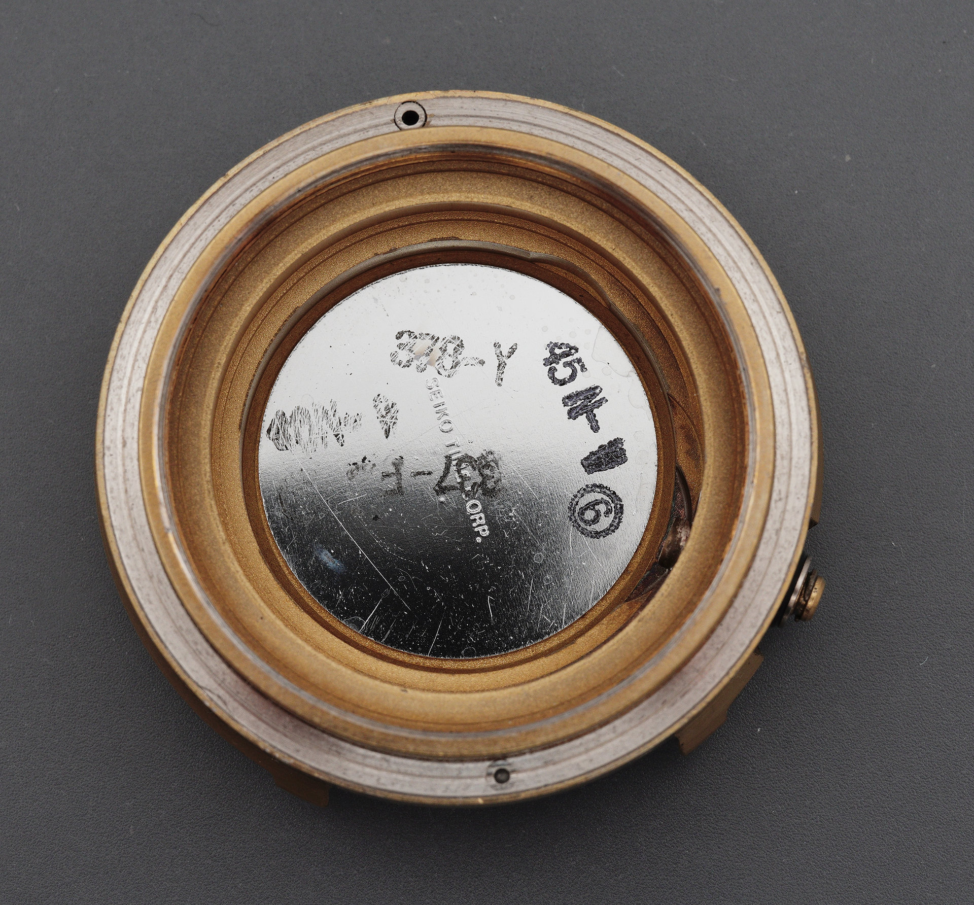
The model number on the rear is 7549-7000 which signifies this as a domestic market watch and which is free of the battery change reminder markings that appear on the case back on the international market watches (ending 7001). Initially, I thought that the codes may have referred to the Japanese calendar years but the numbers, which span 33 to 45 do not fit with the Showa-era calendar years that would have applied for the first dozen or so years of the watch’s life. If anyone can decode the markings, then feel free to illuminate in the comments below. It is worth observing though that the first two digits of the four visible stamps cover the sequence 33, 37, 40 and 45 suggesting battery change intervals of 4, 3 and 5 years after the first battery change. It is probably reasonable to estimate that the first interval would have been around 3 years.
With the movement nestling in a movement holder, its dial and hands now removed, we can start to assess its condition and see if we can get to the bottom of why it wasn’t running. The view from the calendar side provides a very familiar landscape.
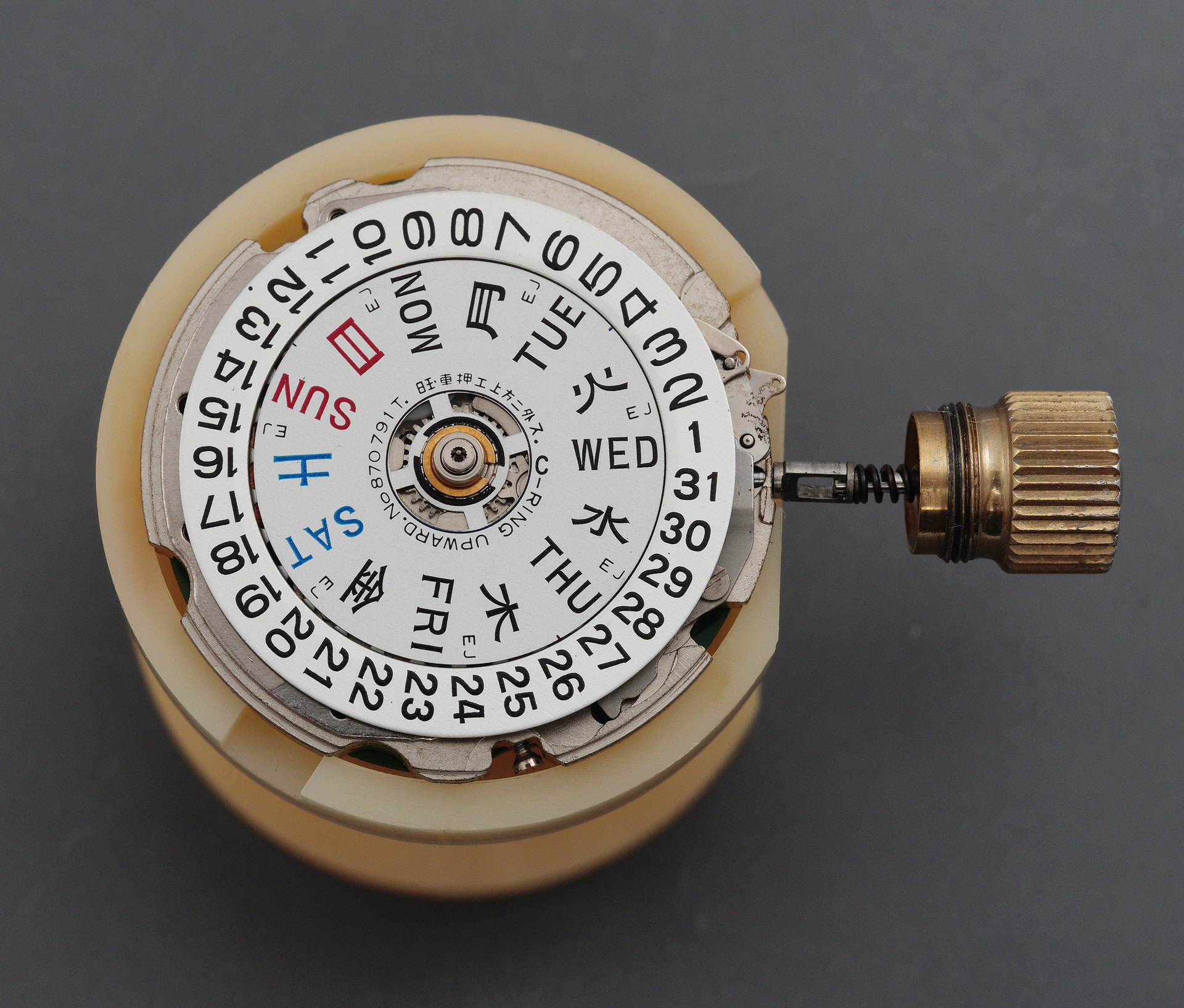
Note the giant hour wheel and canon pinion tube diameters, there to accommodate the oversize hour and minute hands fitted to this huge watch. The Japanese/English day disk is consistent with this being a Japanese domestic market model.
Flipping the movement over and we can check out the train side.
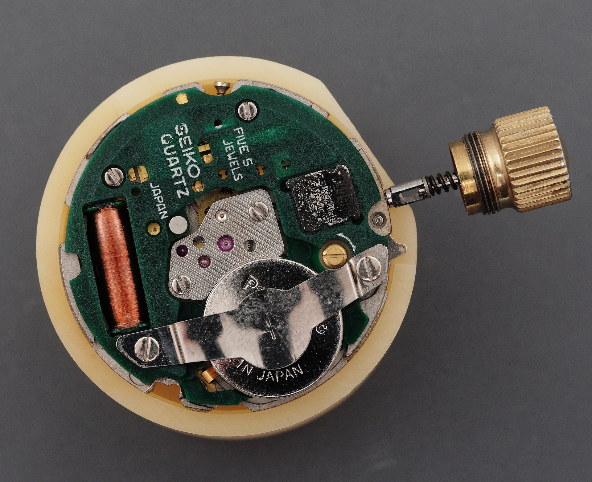
Everything looks spick and span with no signs of battery electrolyte leakage but the movement was not running, even with a fresh battery installed. A quick resistance measurement across the coil confirmed my suspicion that the coil was dead. So, a replacement coil becomes the first item on my shopping list. It is worth noting that although a coil from a 7546 or 7548 would almost certainly work, the part numbers are not the same (4002 750 for the 7546/7548 and 4002 751 for the 7549). The beefier-looking coil fitted to the 7549 is coated in a protective layer of plastic film but I suspect that it may also be rated for a higher current required to drive a movement with the higher torque requirements that result from the very large hands.
As this is a movement family much-featured in the blog previously, we can hop, skip and jump through its disassembly.
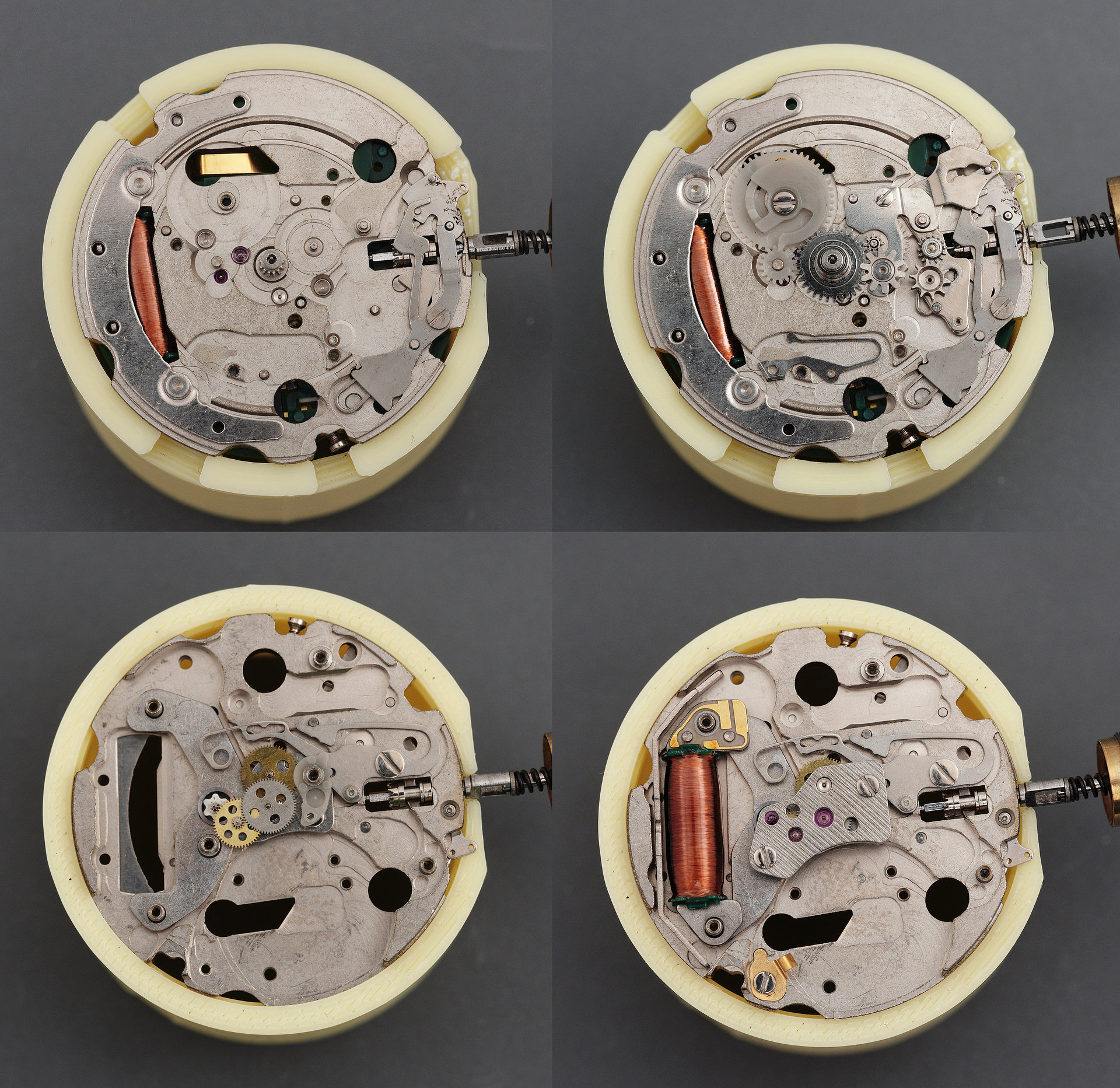
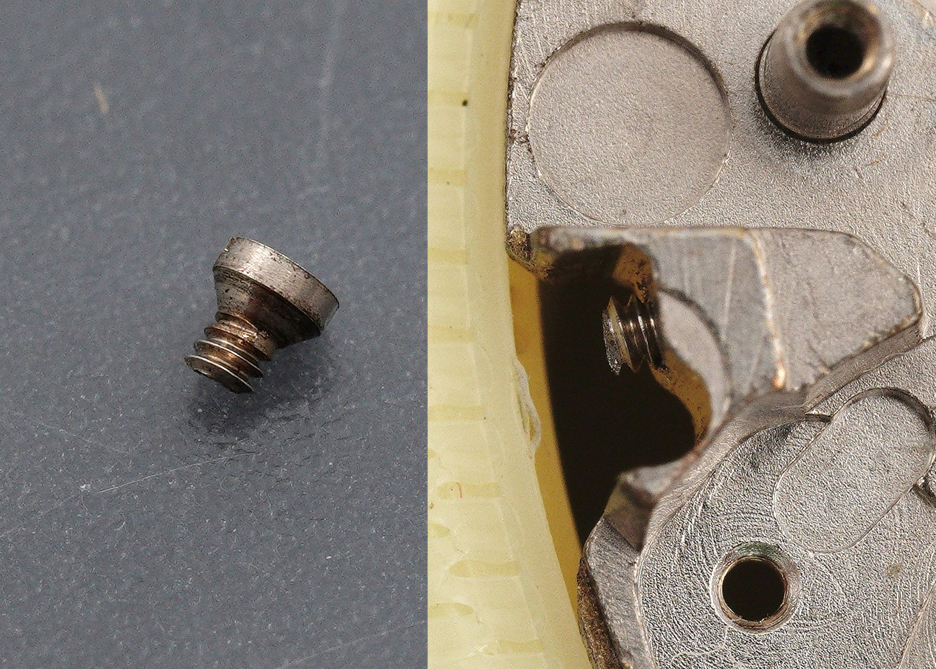
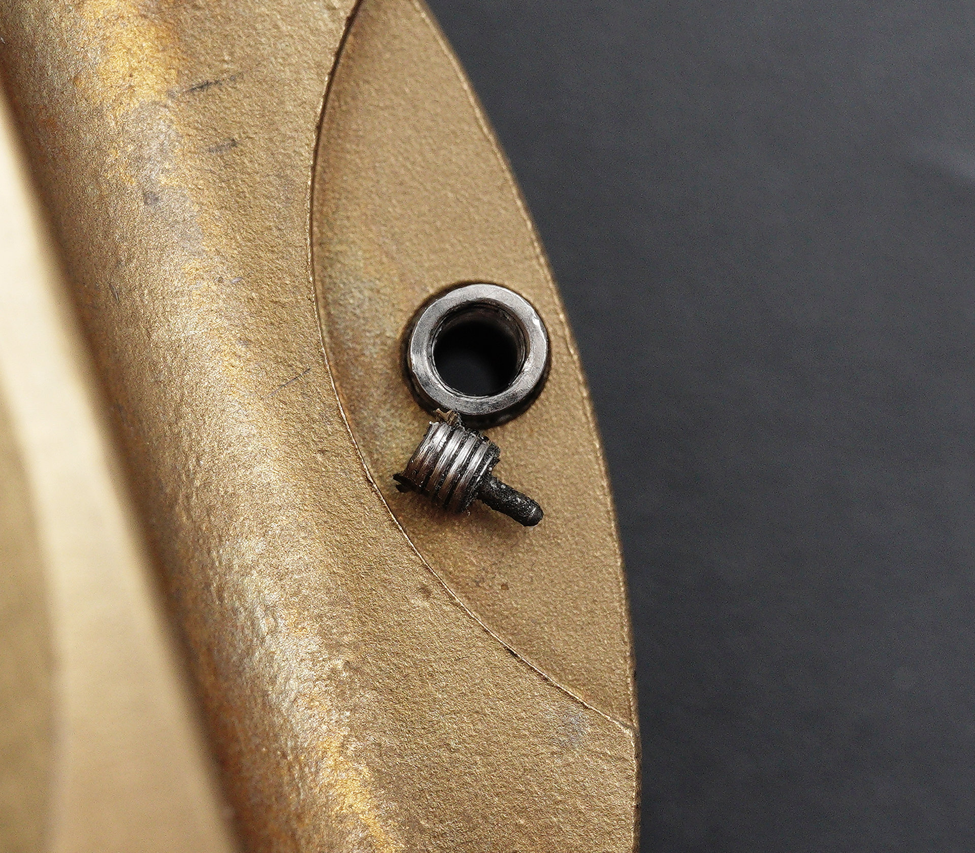
The only hiccough was a broken dial foot screw which required patient extraction of the threaded remnant.
Turning our attention back to the case, let’s see if we can get to the bottom of why the 12 o’clock bezel click ball bearing is missing. This highest-of-end case is designed to allow replacement of the click ball and its spring from the rear (in the lesser diver’s watches, neither were intended to be replaceable at service) – presumably because these watches were designed to be used for extended periods at depth in seawater by professional divers rather than on a more recreational basis by enthusiast divers. If you look closely at the area between the lugs on the rear of the case, you encounter two crimped tube ends, behind each of which lies a screw head.
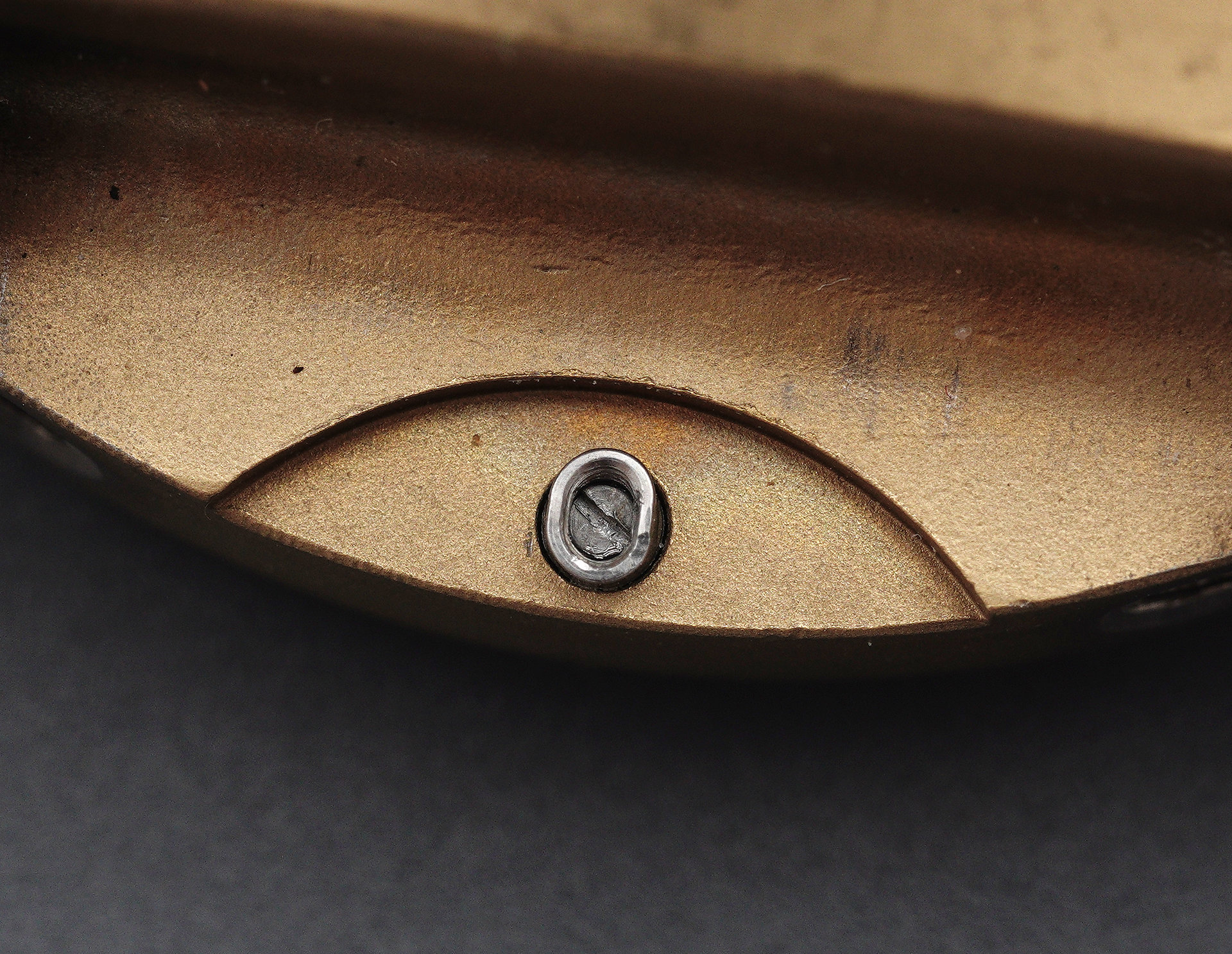
In order to remove the screw, you need to un-crimp that tube. Doing so allows the screw to be unscrewed and removed.
What lies beneath? The answer is: fresh air. No click ball and no spring, both somehow lost in the mists of time. I will figure out how to redress that absence in due course.
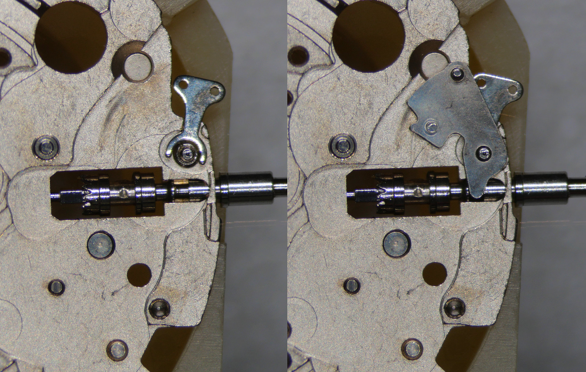
This being a quartz-powered watch, the approach to movement cleaning is a little more circumspect than with a wholly mechanical movement, with electronic and plastic components excluded from the cleaning machine experience, as is the magnetic step rotor and rotor stator. The circuit is cleaned of debris and of any migrated oil/moisture by hand; the step rotor and rotor stator are cleaned in lighter fluid (which is referred to as benzine in the technical manuals) and then dabbed with Rodico putty when dry to remove any fluff and/or particulate matter. Everything else goes through the usual cleaning cycles. The one part that was original to this movement and which I don’t clean is the coil because it is dead but I have in the meantime managed to source a correct part that works and I give that a spruce up with some dabs of Rodico. With all of the movement parts clean, reassembly starts with the slightly tricky balancing act required in order to fit the setting lever, clutch and stem.
The main plate and gear train reconstruction then follows:
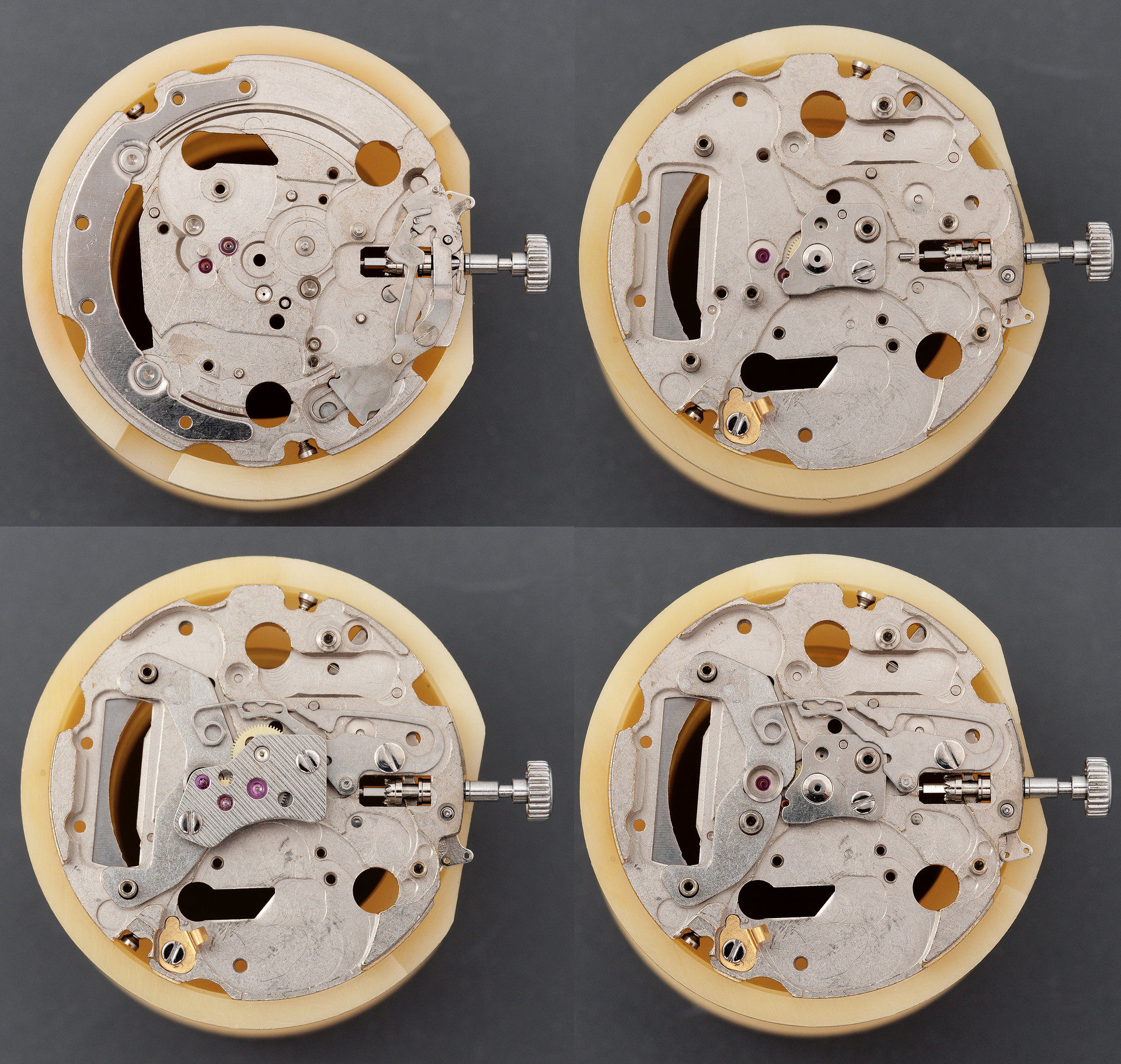
At this point, you will note the presence of both dial foot screws, a replacement for the broken screw having been sourced. The second replacement part comes next (the coil), followed by the circuit, calendar parts, dial and hour/minute hands.
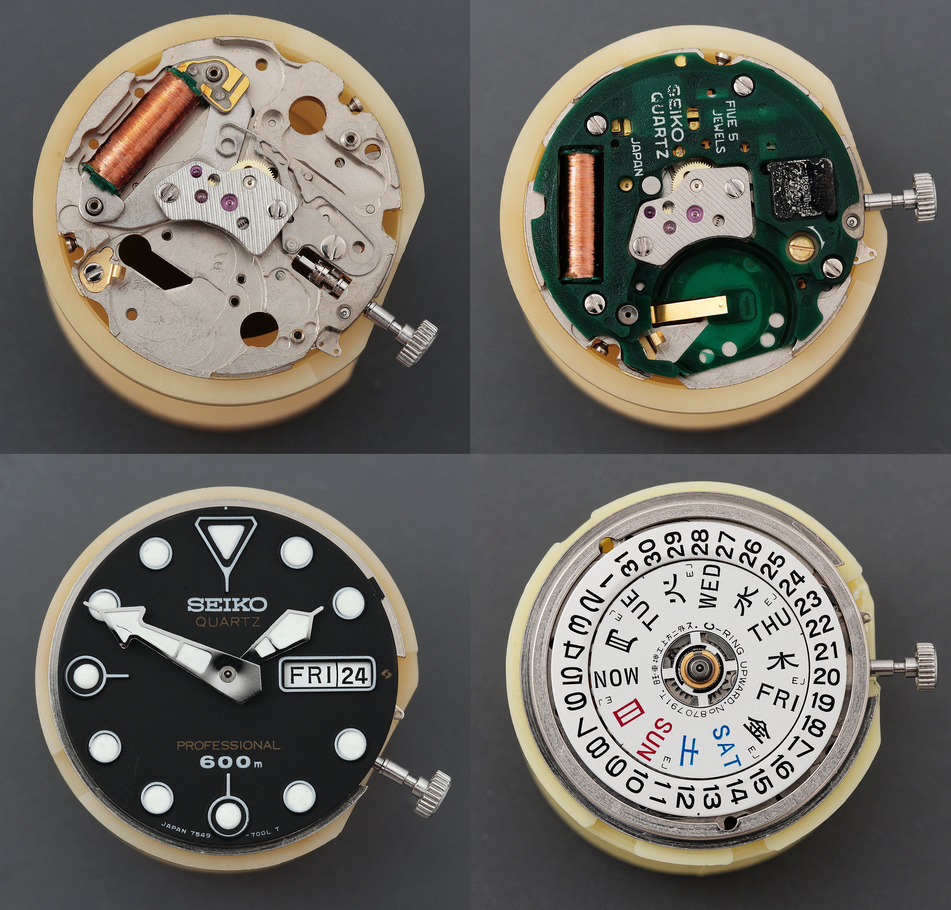
I have left the cracked lume alone at the instruction of the owner, not as the result of laziness! You will note that I have not, at this point, refitted the seconds hand. That is because I had been struggling to get it to align properly with the minute markers and the reason for that turned out to be because the pipe had become detached from the hand, possibly in the same incident that had resulted in the downward bends of the tip and tail. This issue was resolved by re-staking the pipe onto the hand using a domed punch.
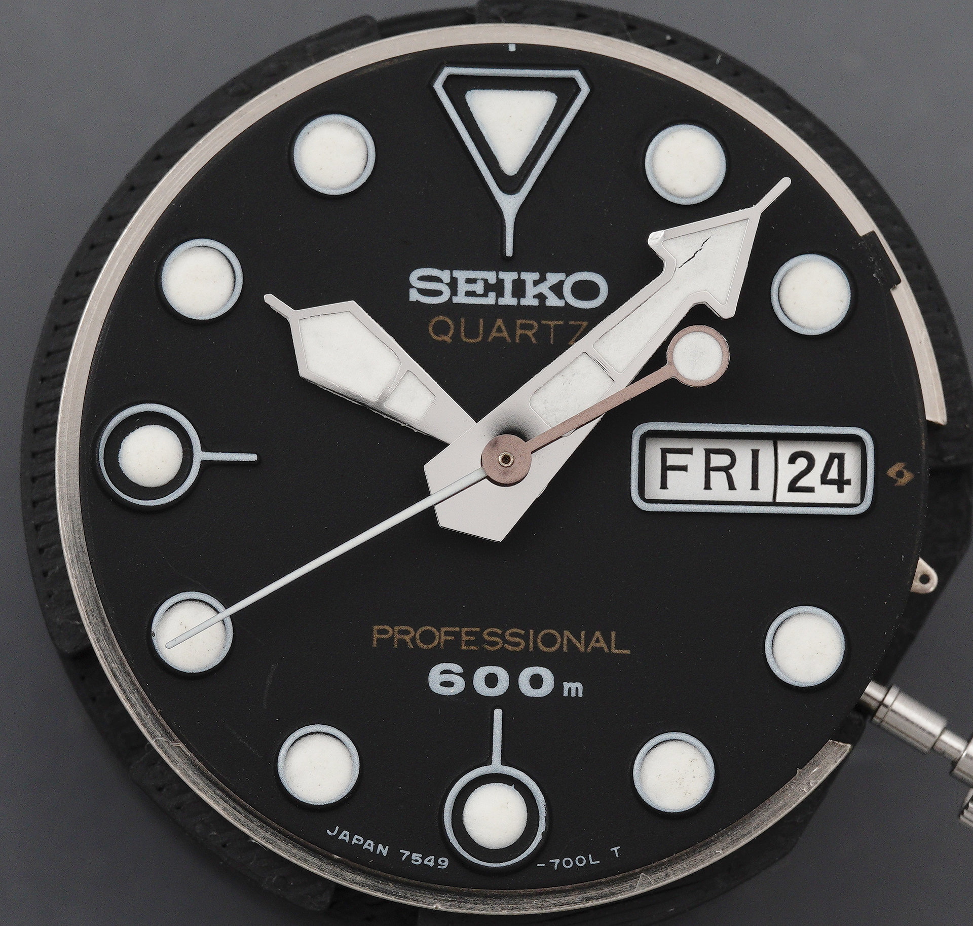
The movement was ready at this point for regulation, its other functions having been given a thorough workout during reconstruction. An initial timing measurement on my Horotec Flashtest yielded a result of +0.3 s/day, a result corroborated by my knackered old Seiko QT-77 Quartz Tester.
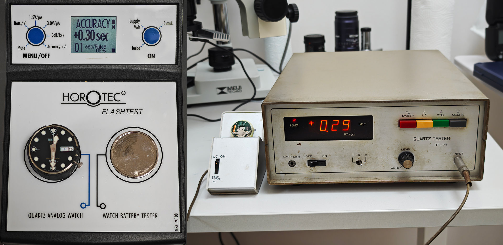
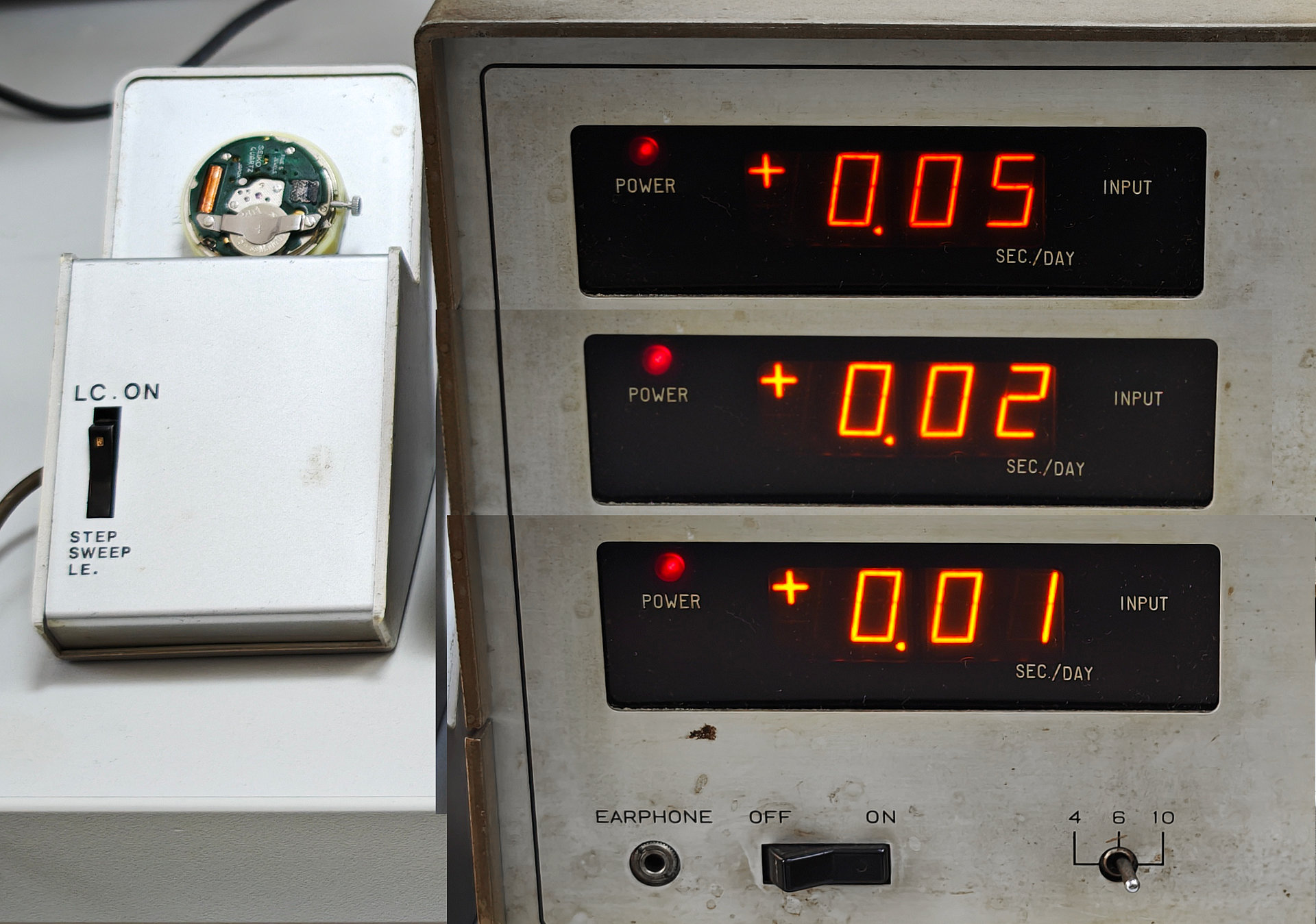
The specified normal rate for this movement is 15 seconds per month gain/loss at normal temperature and +0.3 s/day corresponds to +8.4 s/28 days or, let’s say +9 s/month. That is a good out-of-the-box result but the owner wanted me to see if I could squeeze a bit more out of the movement. That process necessitates the use of the QT-77 because the Horotec requires comfortably more than a minute per measurement to yield a result and tweaking the rheostat one way and then the other and having to wait so long for each tweak to be registered would be somewhat of a tedious process. Happily, the QT-77 yields a timing measurement within a few seconds and so with some delicate tweakery to the rheostat pot, I was able to tease the timing down from +0.3 s/day, to +0.05, then +0.02 and finally +0.01 s/day (at ambient room temperature). That final result corresponds to a rate of +0.3 s/month (with some fluctuation expected with temperature changes). Not bad for a workhorse middle-market late-70’s quartz movement.
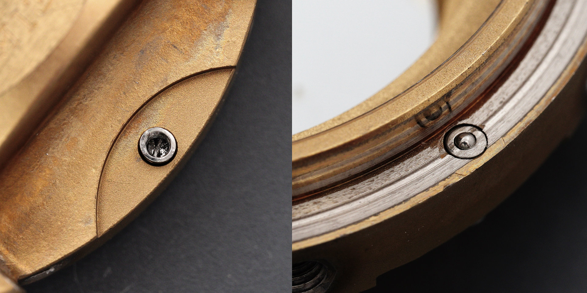
Returning to the now cleaned case, the click ball conundrum was solved having sourced some 1mm steel ball bearings together with a set of 0.9 x 6mm compression springs. Popping the ball bearing, followed by the shortened spring into the hole from the rear, the tension could then be adjusted by tightening the refitted screw from the rear. Some back and forth later and the double click-ball action seems once more to be working.
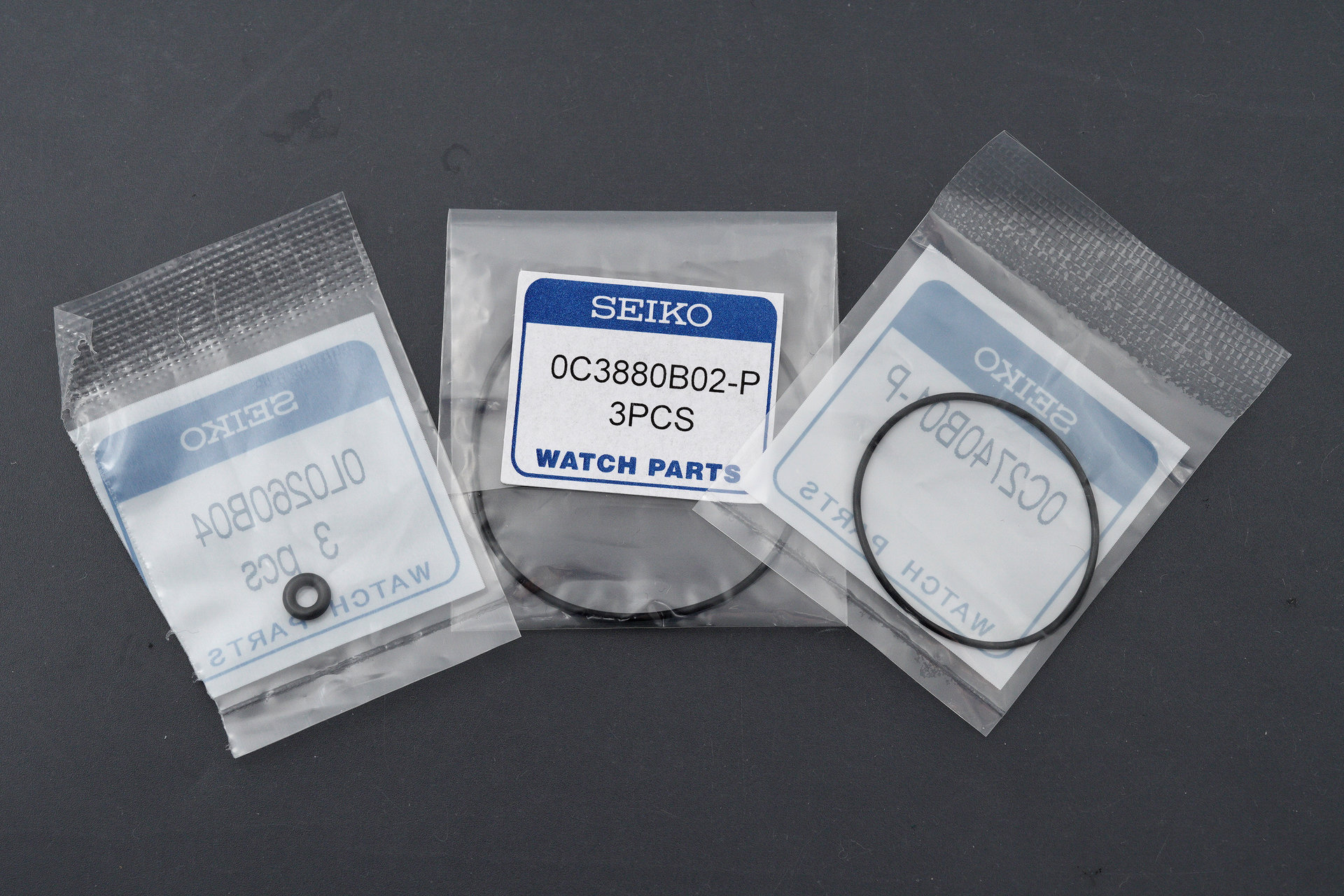
With a fresh set of OEM gaskets for the crown, case and bezel turning ring secured and with the original crystal gasket still in excellent condition and now cleaned, I am in a position to refit the movement and begin to reassemble the casing parts.
The crown gasket is greased and fitted over the tube with the retaining washer and c-clip following. The movement can then be lowered into the case and the crown and stem fitted. The movement fixing gasket then follows.
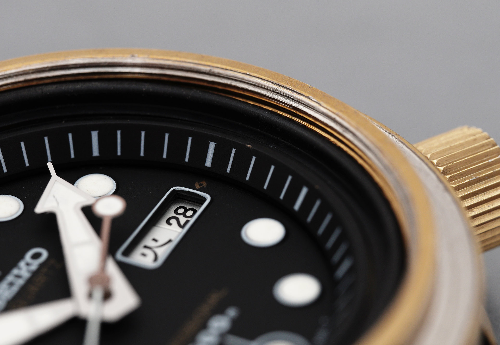
The chapter ring and cleaned crystal gasket complete the next layer.
The original crystal part 335W10GA is still available, at a cost, but not prohibitively expensive given the requirements of this particular undertaking.
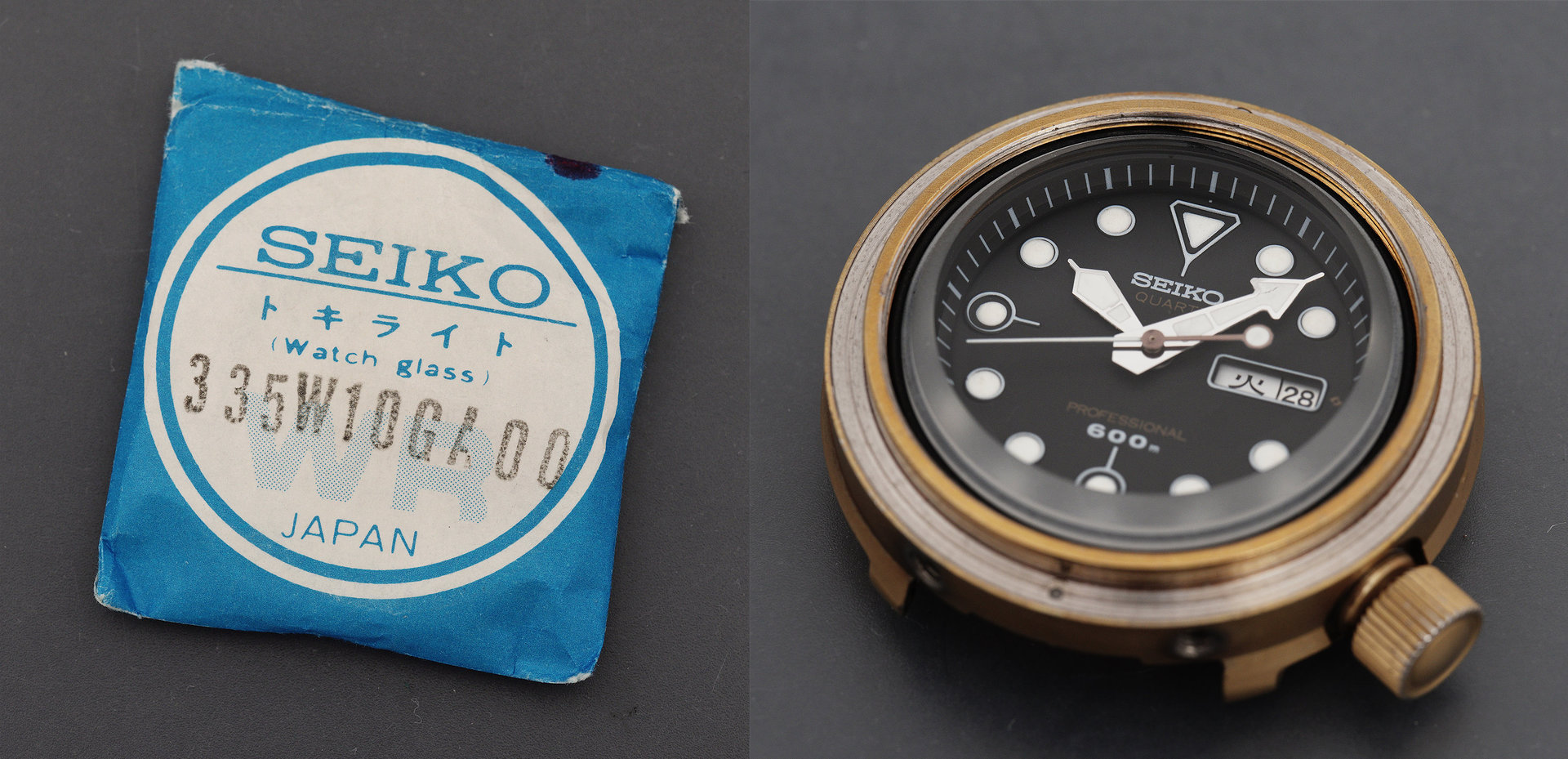
The crystal is properly secured by refitting and tightening the crystal retaining ring, having first refitted the nylon glass fixing ring gasket.
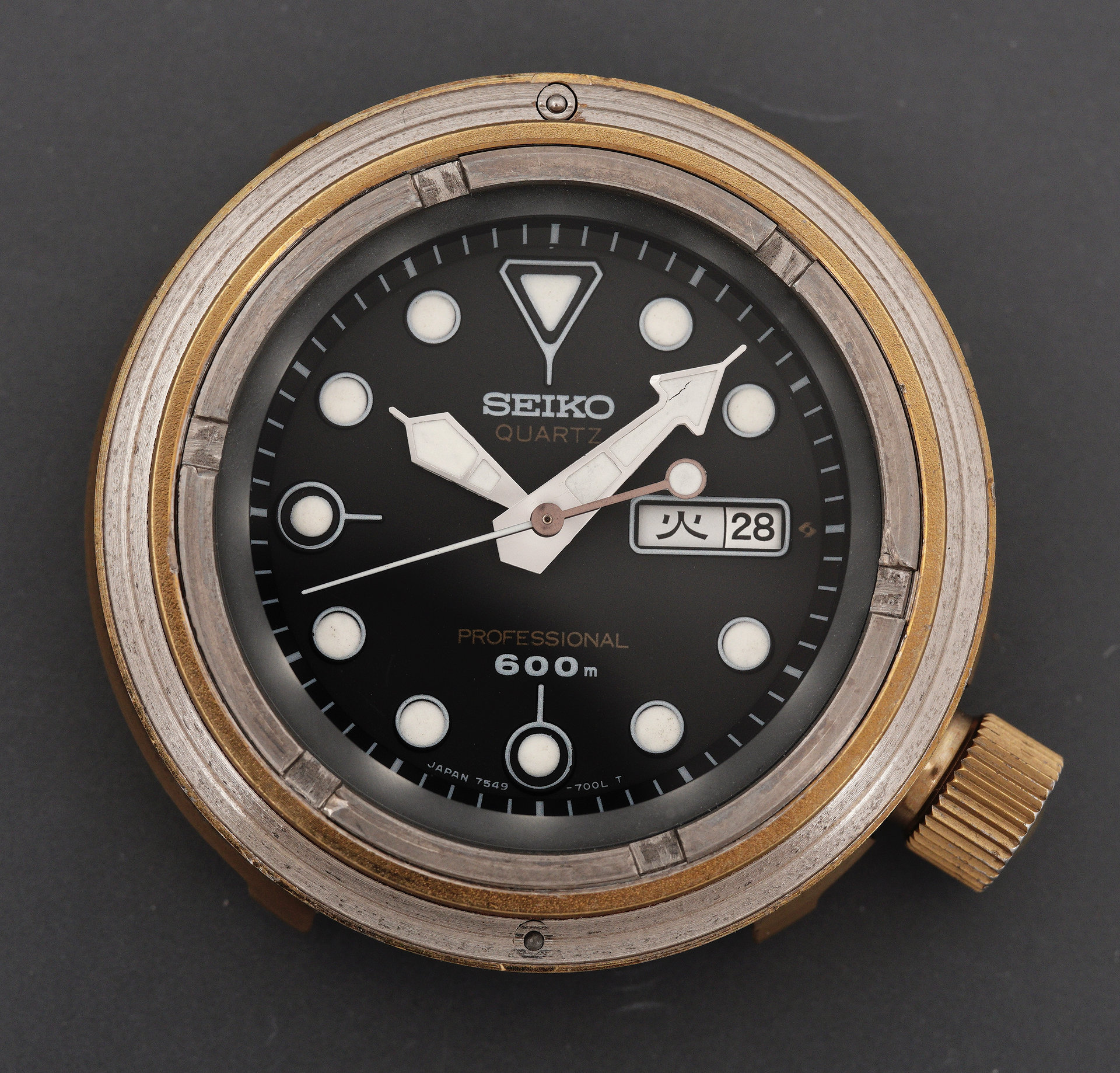
Two further steps to go: a new greased gasket finds its way into the interior groove of the bezel turning ring with that then nestling back into position. I give it a quick rotate in both directions to seat the gasket and confirm that the two click balls are doing their jobs.
And finally, the shroud secures the bezel, with the future retention of the four screws aided by a touch of thread locker.
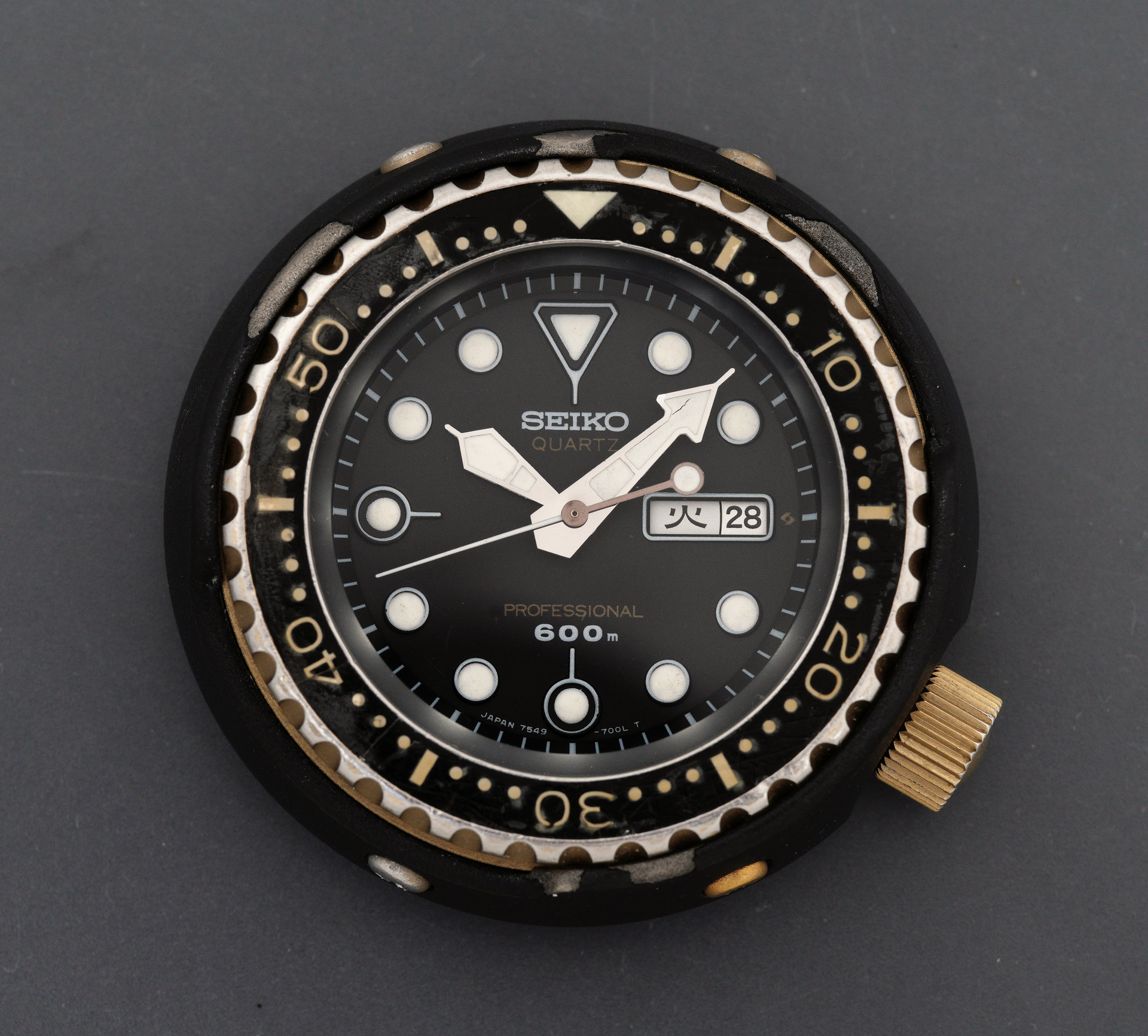
There is no denying that this is an imposing and very impressive piece of hardware, one whose unique design language pays tribute to the innovative, clean-sheet thinking of the original design team.
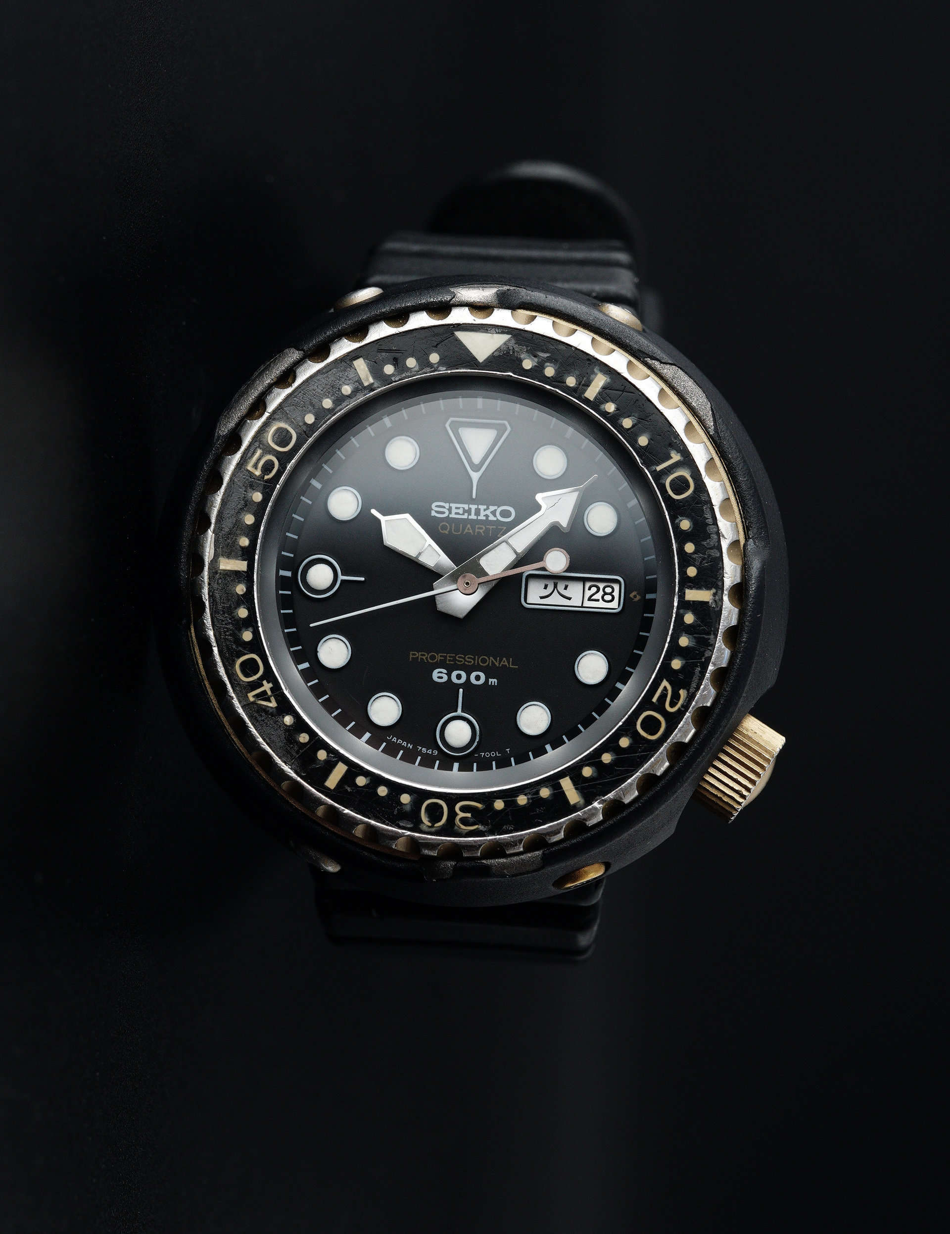
The result was a watch almost uniquely fit for purpose, liberated as it was from the dilution of tool watch pretentions that comes with watches intended to appeal also to aspirational buyers more concerned with how a watch sits under a shirt sleeve or the messaging that it broadcasts to their peer group. I like this particular watch for the way in which the life well lived radiates in its scars and patina, all of which serves to enhance its personality and its character.
The sense I have though is that this sort of tool watch has been made redundant by modern wrist-worn dive computers and that is reflected in the messaging conveyed in the latest Seiko catalogues that suggest that the Tuna may be reaching the end of its life. All the more reason then to treasure these surviving examples and when opportunity knocks, provide them with a new lease of life.

