
The heart of every mechanical watch movement is the balance, whose role is to control the release of power from the mainspring. It performs this task in a highly regulated fashion, each swing of the wheel permitting a precisely-timed incremental motion of the gear train. It is vital to the task of marking the progress of time accurately but its role as a regulating middleman is singular. This basic function has been served in every lever escapement mechanical watch and clock movement from the mid-1800s to the present day. However, for a brief period between about 1966 and 1976, the lever escapement balance evolved to become the driving force behind the power rather than just as a regulator. It assumed this dual function in that stop-gap technological blind alley, the electronic balance-driven watch movement.
The powered motion of the balance wheel in an electronic watch movement derives from interactions between magnetic fields produced by the current passing through a static coil and permanent magnets fixed to the balance wheel. The earliest electric balance movement was developed by Hamilton in the late 1950s and used delicate and unreliable contact-switching to reverse the polarity of the field between each swing of the balance. However, the introduction of diode-switching (LIP) and subsequently transistor-switching (Citizen and ESA) solved the reliability issue and the technology reached a sufficient degree of refinement to sustain these watches as a commercially viable stop-gap between the traditional mechanical movement and the stepper-motor controlled quartz movement that was to assume its dominance from the early to mid-1970s, rendering the mechanical movement effectively redundant.

ESA’s Dynotron movement of 1968 is widely-credited as the first to employ a balance wheel and a transistor, but evidence suggests that the Citizen Cosmotron released in 1966 was ‘the world’s first genuine electronic wristwatch [with] a moving-magnet type balance motor, driven by transistor on the regulating device’.
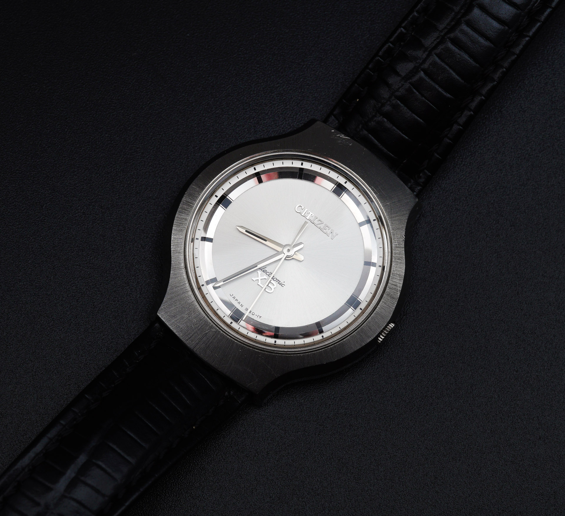
I have written previously about two examples of Seiko’s foray into the electric watch arena in the EL-370 and Elnix models, but in this present article we will wind the clock back a little and take a look at the root of the phylogenetic tree that is the transistorised electronic balance-driven watch: the Citizen Cosmotron. The earliest iteration of the Cosmotron was branded as the Citizen X8 Electric watch, fitted with the 25 jewel 0801 calibre. Subsequently, its branding changed to Chronomaster X8, with or without Chronometer status, as indicated by additional wording on the dial. At some point in its history, it switched from the Electric X8 to the Electronic X8 but it is not clear to me whether that came towards the end of its production life or relatively early (see discussion below). The example that forms the basis of this present entry is either wholly of very early vintage or is an amalgam of early exterior and later interior parts.

I bought this example during a frenetic period last year in which acquired examples of a number of electronic, quartz and mechanical Citizen watches from my favourite period (early ‘60’s to late 70’s) of horology. The serial number on the rather extraordinary case back suggests that this example dates from December 1965 and the branding, that of the Citizen Electric Watch, in contrast to the dial which uses the term ‘Electronic’.*
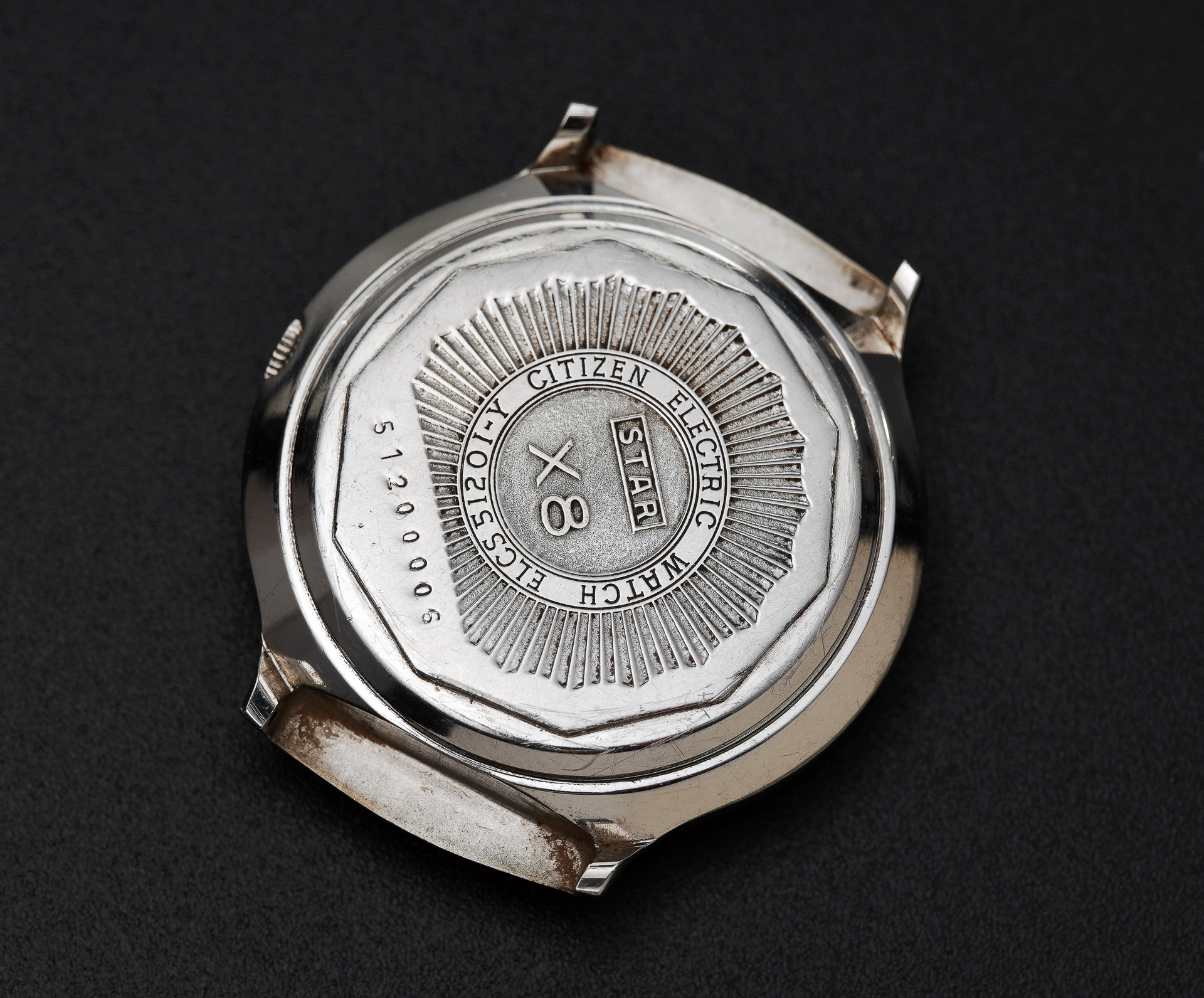
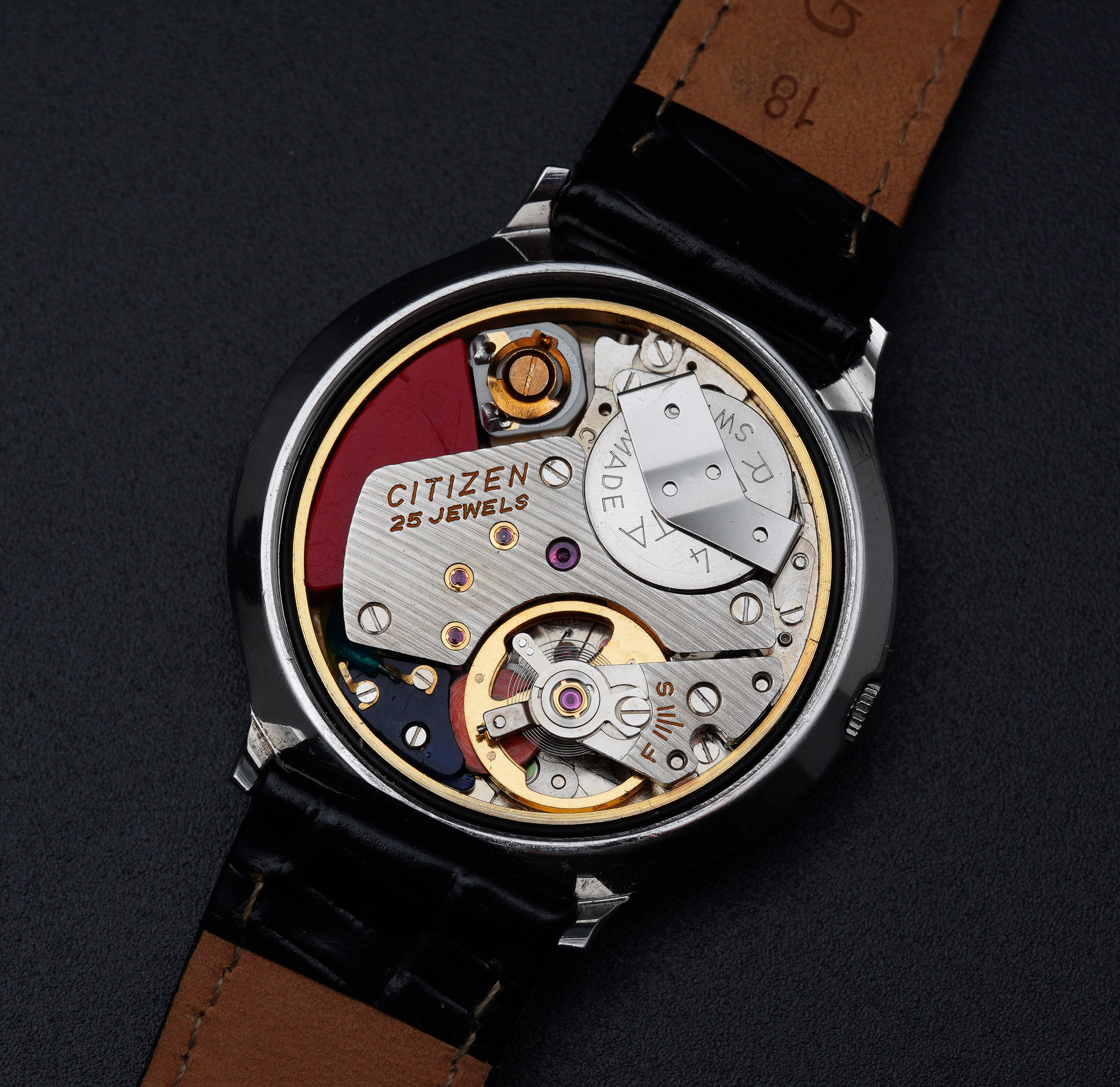
The case is in excellent condition with the vertical brushing still very crisp and only marred in a couple of places by scuffs. The dial and hands appear to be in very nice condition, although the hands have tarnished to a brownish hue. The case back requires, in principle, a special ten-sided caseback wrench but I was able to unscrew mine using the flat-sided prongs on my heavy-duty caseback opener. The movement revealed beneath looks complete and undamaged but predictably tarnished, in line with the extended passage of time since its last service.

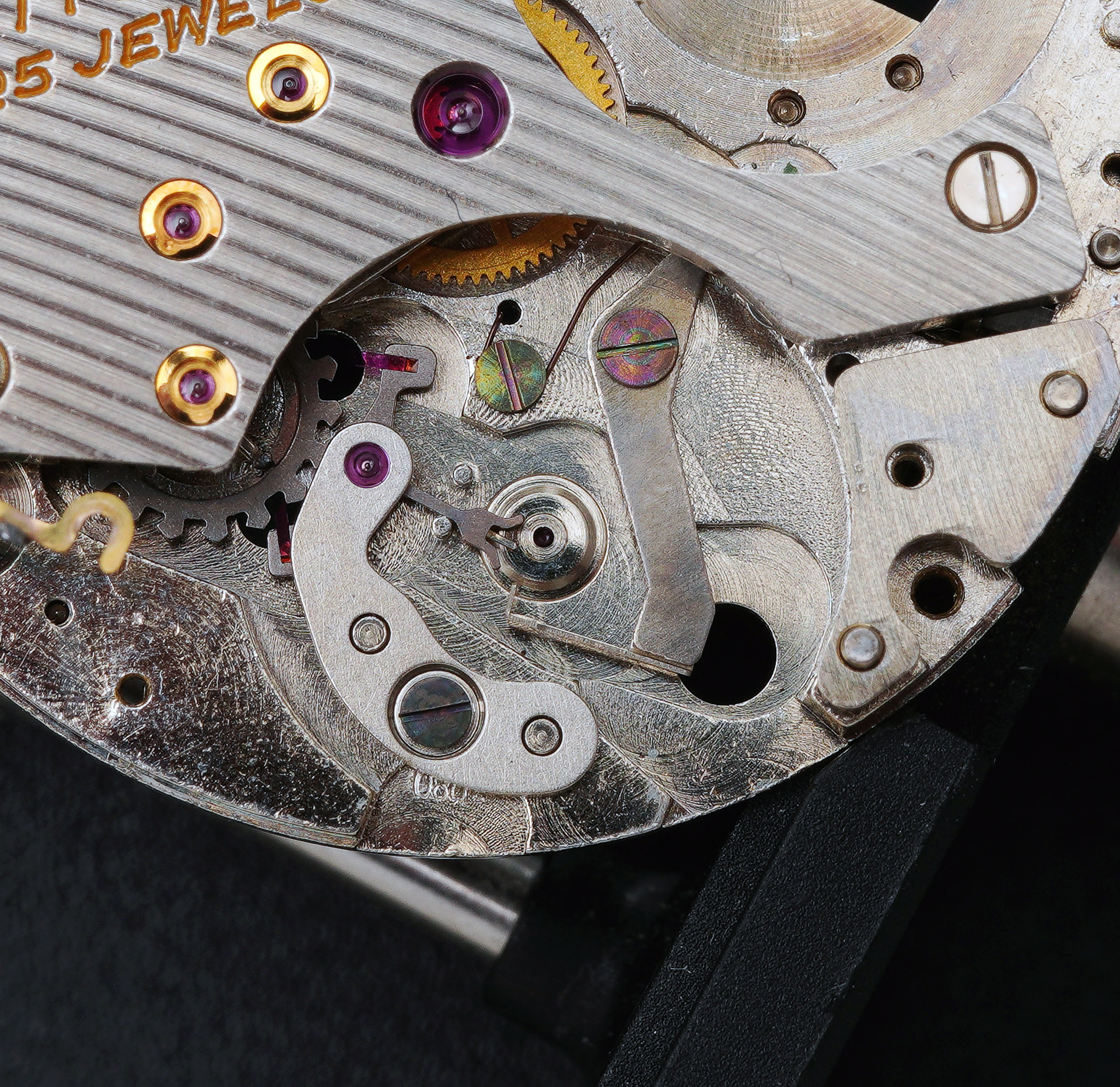
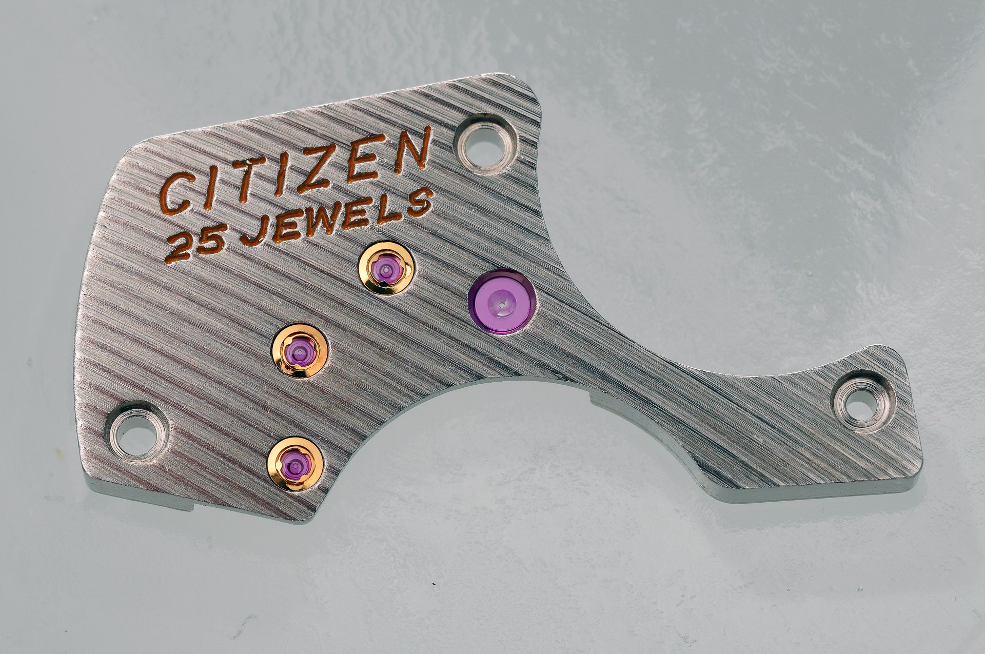
What is apparent to me straightaway is that this is a high-quality movement, very nicely finished and decorated, and equipped with an extravagantly large number of jewels for an electronic movement. The depth of quality aligns with the relatively high asking price when these watches were first introduced. It is tempting to speculate that the high jewel-count may have benefited from the use of redundant jewels to bolster their number but as I was to discover, there are no such dummies. Yes, it is arguable that this movement really needs six Profix capped settings but those additional six jewels do actually serve a purpose. Even if you discount these cap jewels, the jewel count is still 19 and this is a movement without a mainspring and barrel and without an automatic winding device. Every pivot in this movement benefits from a jewelled bearing. But I’m getting ahead of myself. Let’s press on.
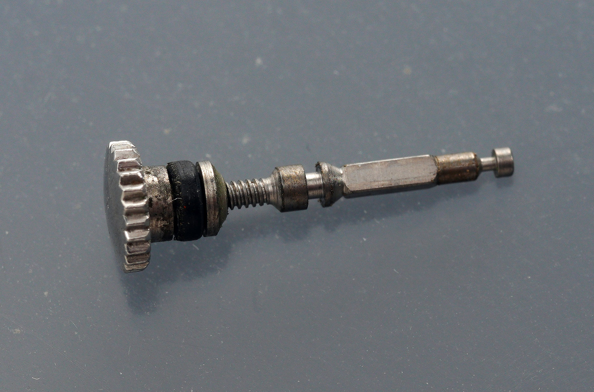
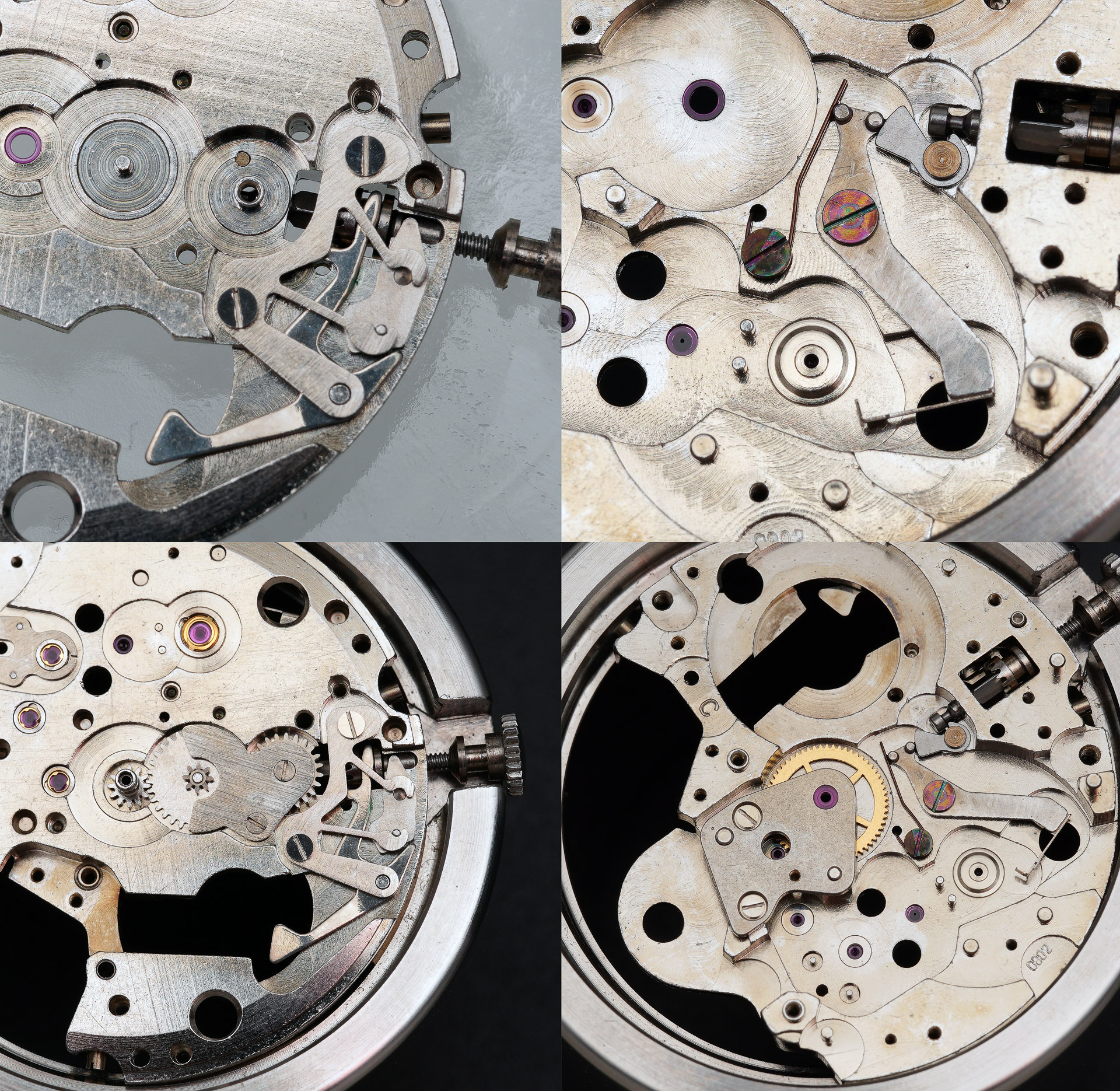
The stem is released by depressing the setting lever button located between the base of the balance bridge and the battery terminal.

The stem itself has a surprisingly blockish, chunky appearance.
The condition of the dial and hands with the movement released from its confinement is at least as good as first impressions suggested, with mild tarnish and a bit of dirt being the only blots on the landscape.

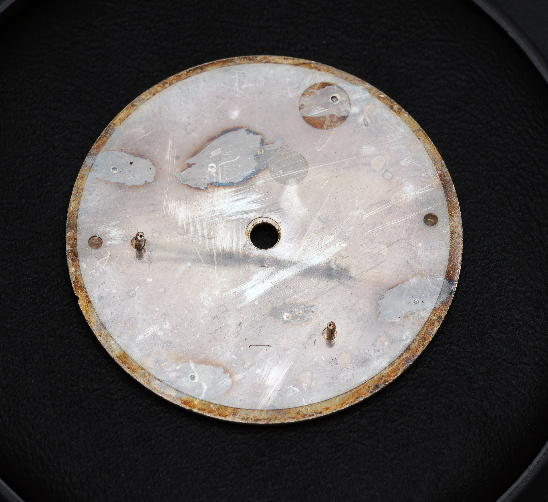
With the hands removed, we see that the dial is secured conventionally by a pair of dial screws that grip two dial feet.

The dial feet themselves are located within the same tertile on the rear of the dial, presumably because of the amount of real estate occupied by fresh air in the main plate (to accommodate the circuit blocks).
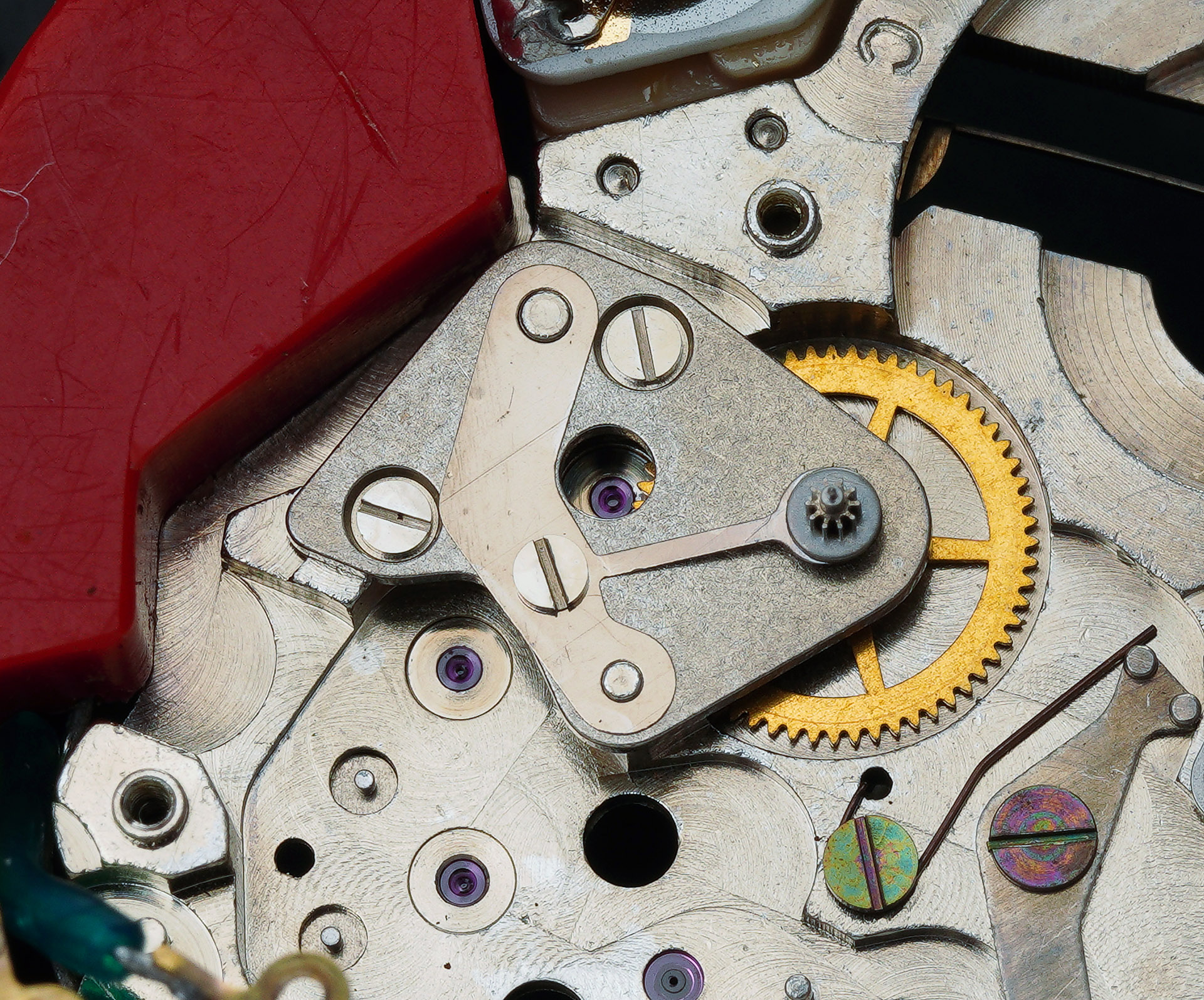
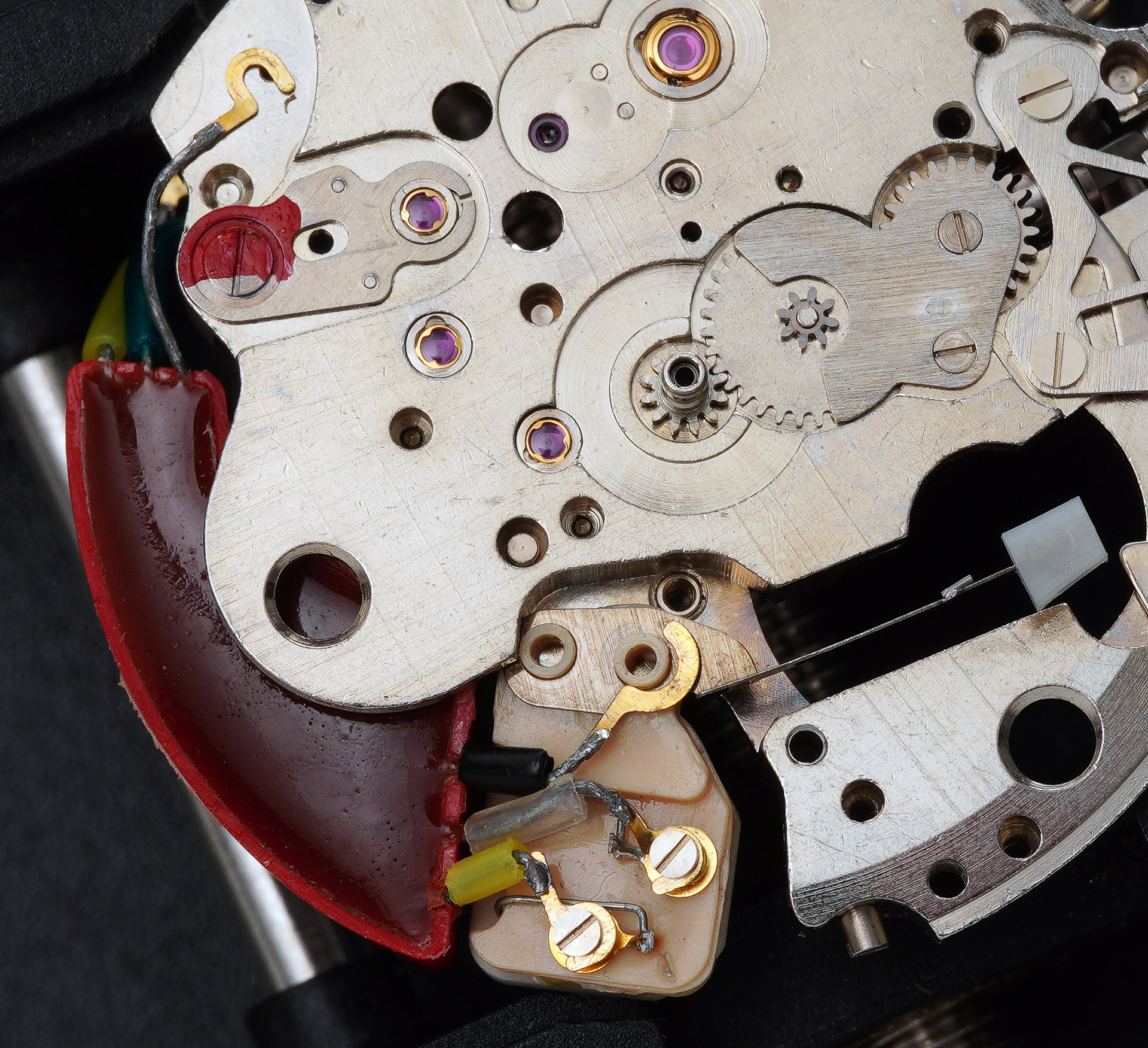
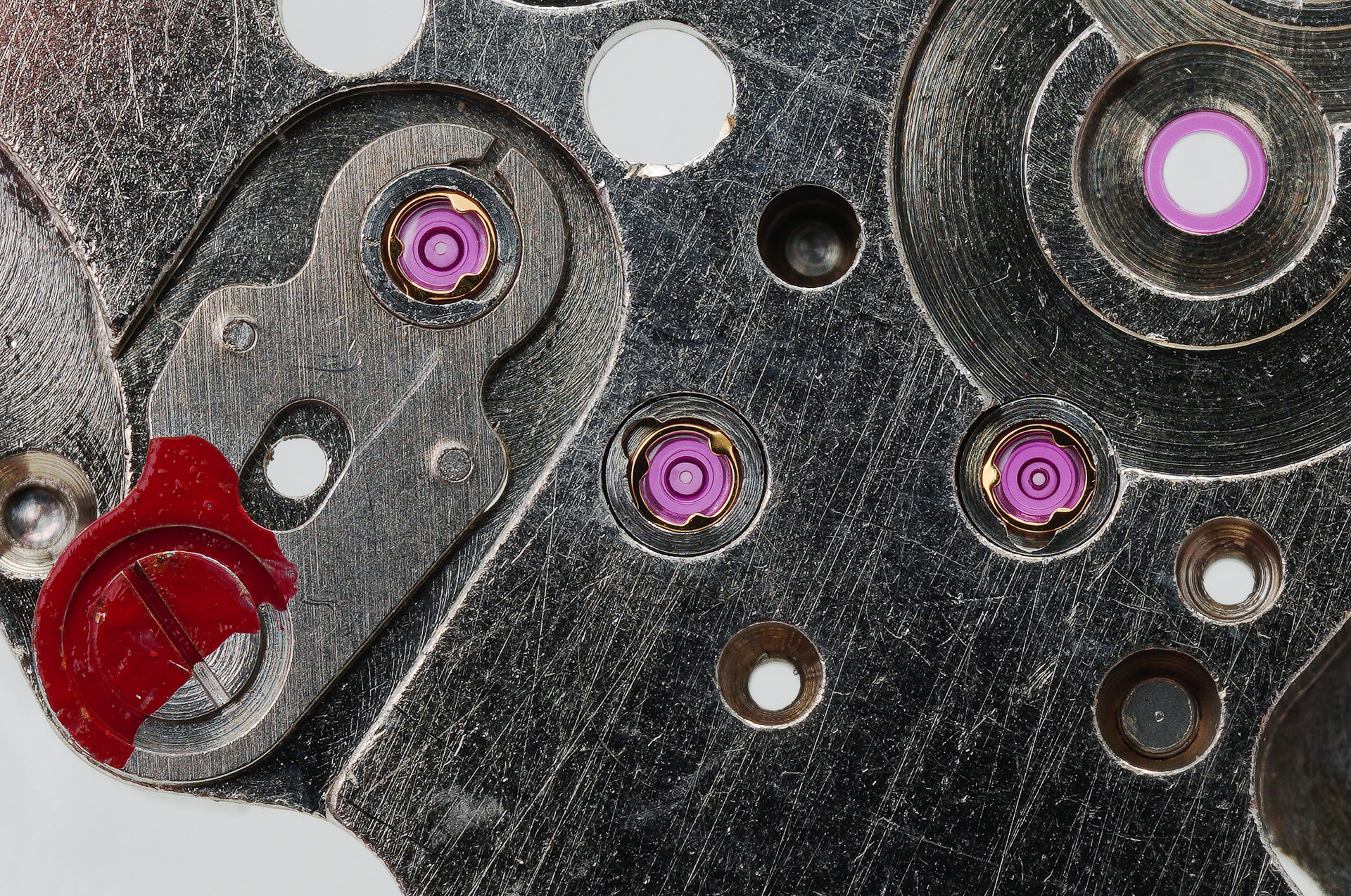
Note the insulating plastic film covering the rear of the dial. A few highlights to note on the balance side of the movement, clockwise from top left, below: The negative terminal sits unsecured in its hollow; beneath which we see a sprung switch that completes the circuit when the crown is pushed into its resting position; the characteristic Citizen Parashock setting protecting the balance staff; and three of the six Parafix, oil preservation settings.

These photographs illustrate more clearly just how tarnished the movement is, with most of the surfaces darkened by a hard layer of varnished oil vapour. The dial side better reveals why the two dial feet are located so close together:

A significant amount of the surface area of the main plate is cut out to provide room for the circuitry and the sprung switch mechanism. Presumably the designers wanted to locate the second of the two dial feet screws well away from the balance which means that the two sit on an arc about 120 degrees apart. This perspective also provides a view of how the sprung switch interacts with the setting mechanism. We will see later that it works in concert with a hacking lever acting upon the balance wheel.
The next job is to remove the three Profix cap jewels from the balance side as well as the Parashock setting from the balance.

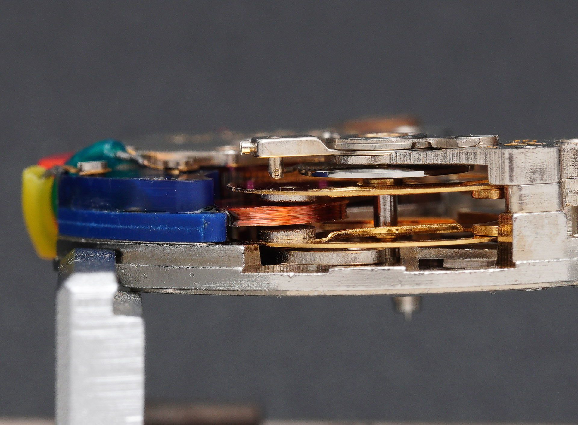
In a conventional mechanical movement, the balance would be removable at this point but in electronic movements, you have first to remove the coil assembly that sits between the two parallel balance wheels.
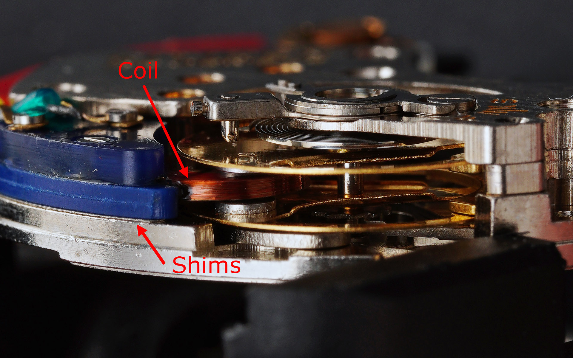
Notice the two shims beneath the coil assembly, there to fine-tune the position of the coil between the magnets mounted on the balance wheel. Removal of the coil requires the two connecting wires to be disconnected and the mounting screw removed and the whole part comes away as a single item, revealing the two shims beneath.

The balance assembly can be lifted out at this point, no longer impeded by the presence of the coil. The curious star on the underside of the balance wheel is there to mesh with the hacking lever when setting the time. I presume that it is necessary because the mass of the balance wheel might otherwise make stopping the balance more of a challenge for a stop lever that just makes contact with the edge of the wheel itself.
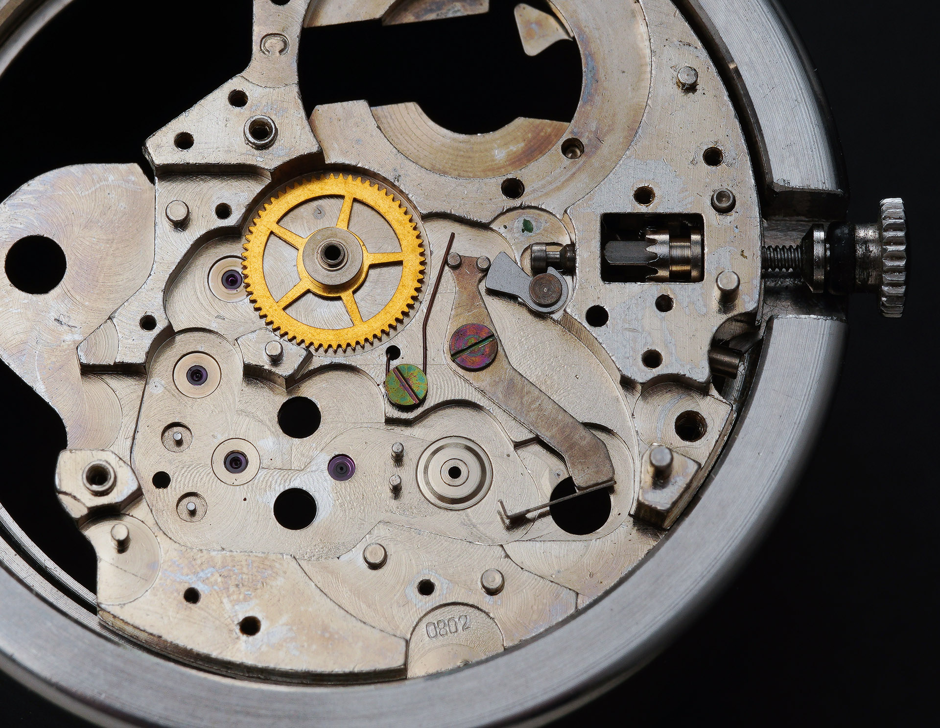
With the coil and balance out of the way, the next task is to remove the train bridge, exposing the going train beneath.

The five components on display in the photo above, clockwise from lower left are: the escape wheel (which effectively functions as the first wheel, in place of the barrel and mainspring in a purely mechanical movement); the second wheel; the intermediate wheel; the sweep seconds pinion; and beneath the centre wheel bridge, the centre wheel. The sweep seconds pinion is supported beneath by a friction spring.
The circuit block, complete with lever stop, can be detached having first removed three screws, two at the base of the lever stop which secure the block to the main plate, and one at the other end of the block to untether an earthing wire.
The circuit block and main plate part company, the latter now also free of some of its jewellery.

The final steps before cleaning require us to remove the centre wheel, disassemble the stop seconds lever and, over on the other side, the setting parts.
All of the movement parts except for the plastic and electronic components are transferred to the cleaning machine for their shampoo and blow dry. In spite of my best efforts though, the varnishing of the main plate and bridges proved very difficult to eradicate entirely and so, even after a thorough two-stage clean and two-stage rinse cycle, retain a degree of patina. Nevertheless, the movement is otherwise spotless and I am ready to climb the entropic hill.
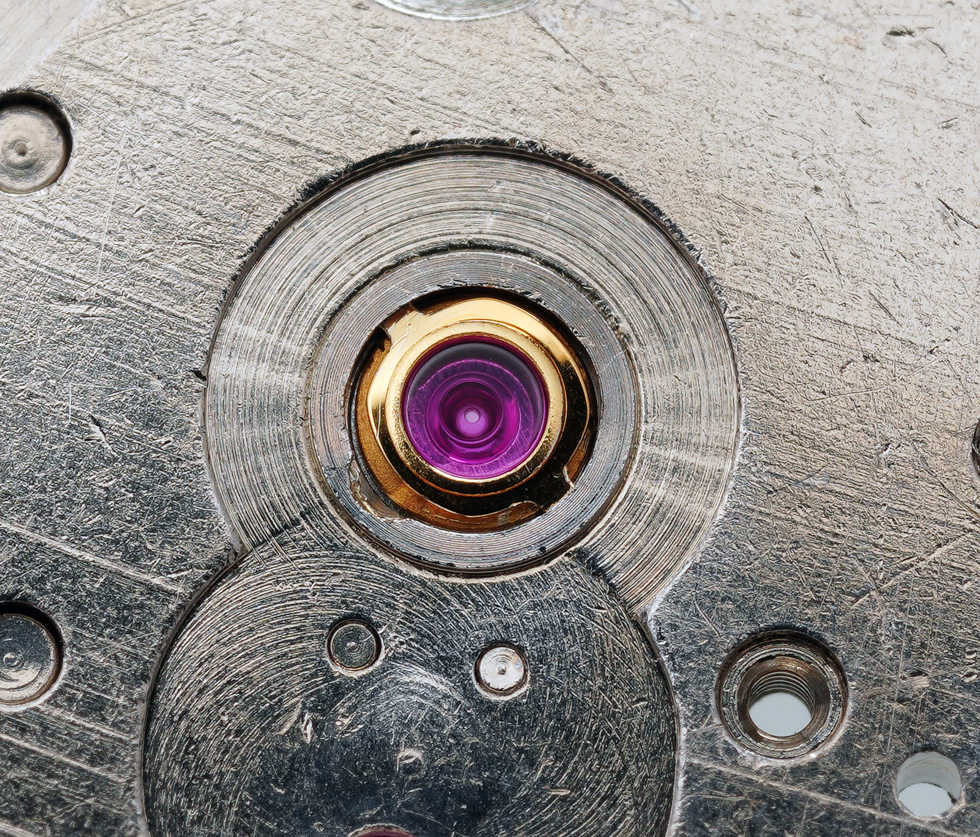
We start with the six Parafix settings, three on the train bridge and three on the dial side of the main plate.
This is a fairly fiddly business and fraught with the potential hazard of over-oiling from the rear but as you may be able to see from the two preceding photographs, I achieved six neat, round oil reservoirs for each of the six settings. The first of the two Parashock settings comes next, this one on the dial side of the main plate.
The next steps are straightforward enough: the stem, clutch and setting parts; the stop seconds lever and its spring; the centre wheel and its bridge; and then the cannon pinion, minute wheel and its bridge.
I should note at this point that although I do have a low-resolution image of the exploded movement to refer to, I do not have the technical manual and so the order of play here is me following my nose.
The circuit block is refitted at this point, following a careful wipe down, and the earthing wire at its tail reconnected on the dial side.

Comfortably the most infuriating task follows: fitting the train bridge. I am struggling to think of another occasion in my experience in which all four pinions refuse to stand to attention in a way that allows the simultaneous location of their eight pivots into their eight jewelled holes. Somehow, I manage the task but it is not something I would relish repeating in the near future.

With that horrible job completed, I can fit the pallet fork and its bridge.

It is good to see the balance back in position next, although we still have a few steps yet to complete before we see it swing back into action.

The first of those is to refit the coil, initially complete with both shims.

A side view shows perhaps that the coil is sitting a little closer to the top tier of the double-decker balance but we can also see that quite a lot of debris is adhered to the magnets.
Rather than removing the whole lot again to clean the magnets, I opted to swing the balance out to provide access to the magnets and the attention of the sticky side of a strip of Sellotape.
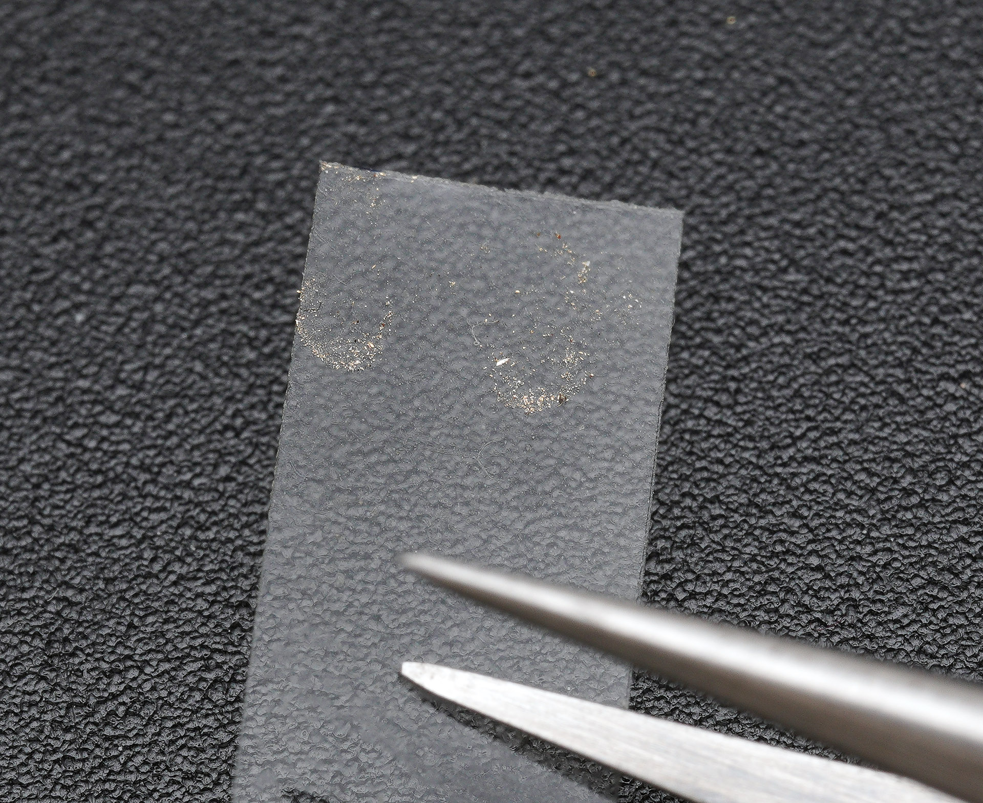
I performed this operation four times, twice for the top pair of magnets and twice for the bottom pair. The completion of the circuit requires the negative terminal to be in position and I deduce that we also need to have fitted the dial to provide a secure backstop to the setting lever spring that closes the circuit to the rear of the terminal.

First though we have to dispose of some copper salts that have grown around both sides of the column at the centre of the terminal.
The part you see in the photo above is what makes contact with the central part of the spring shown in the previous photograph. With the dial back in position, its rear insulated from the circuit by an insulating membrane, we can refit the negative terminal and contemplate our selection of a suitable battery.

This turned out to be a less than straightforward process. The original battery for this movement would have been a 1.55V silver oxide battery – possibly an LR43 – but initially I struggled to get the most suitable modern replacement – a 344 – to work. I could get the watch running with power supplied by my quartz tester but not with a battery in situ. Initially I suspected that the spring to the rear was not making a sufficiently good contact and so adjusted the spring – but still I could not get the watch to run. By a process of elimination, if the spring was making contact with the terminal when the terminal was depressed, but no juice was flowing with the battery in position, then the battery must not be exerting enough downwards force to make the connection between terminal and spring. I surmised that this must be because the negative protuberance on the modern battery was insufficiently deep to depress the terminal tab downwards to make contact with the spring. My second thought was that, in addition to it not protruding enough, the width of the protuberance was shorting the terminal to ground. Both turned out to be the case, as revealed by my sequential attention to one and then the other issue.
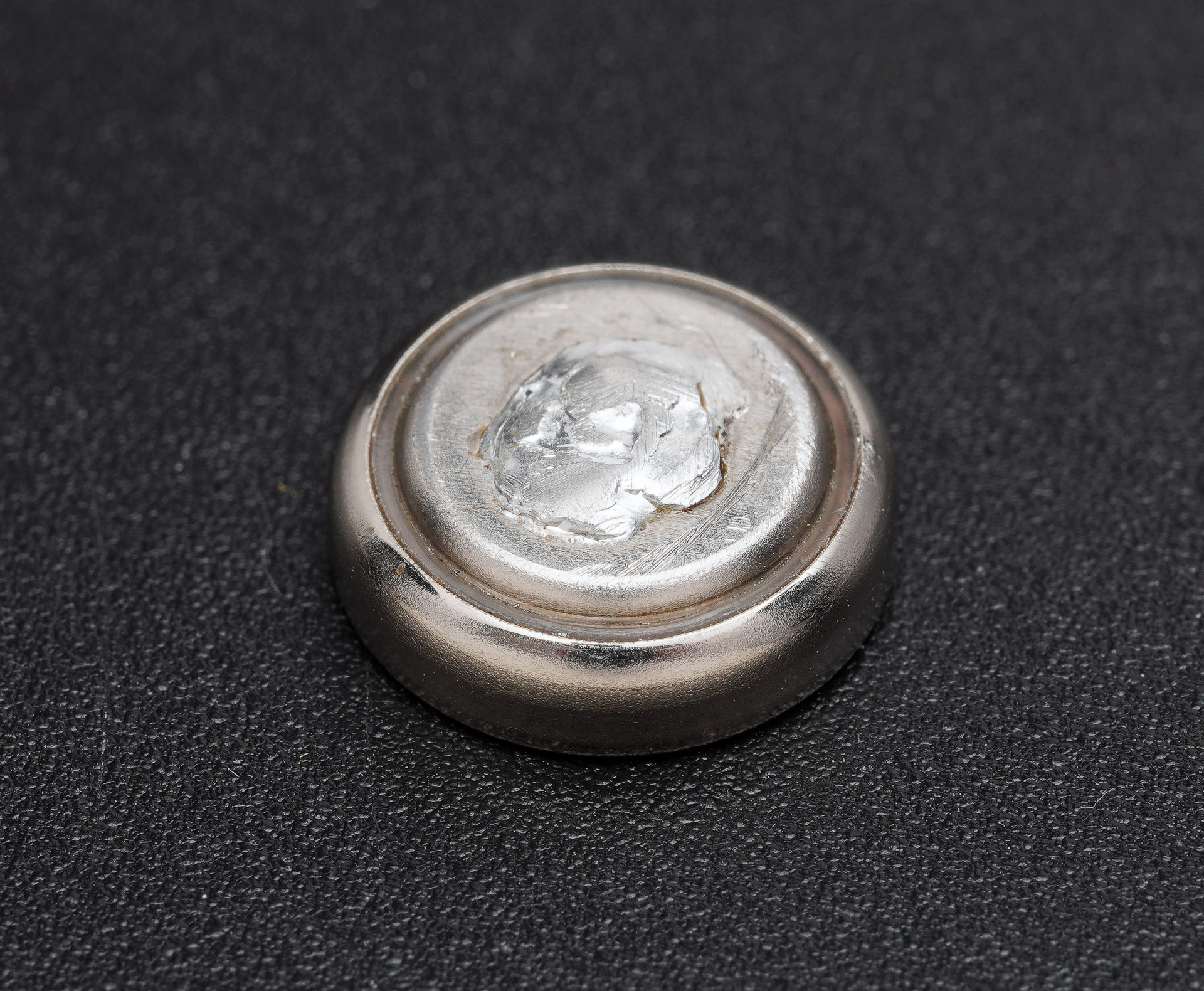
The solution to the first of these issues was somewhat Heath Robinson – I simply soldered a lump of lead solder to the negative side of the battery, thereby extending its overall height.
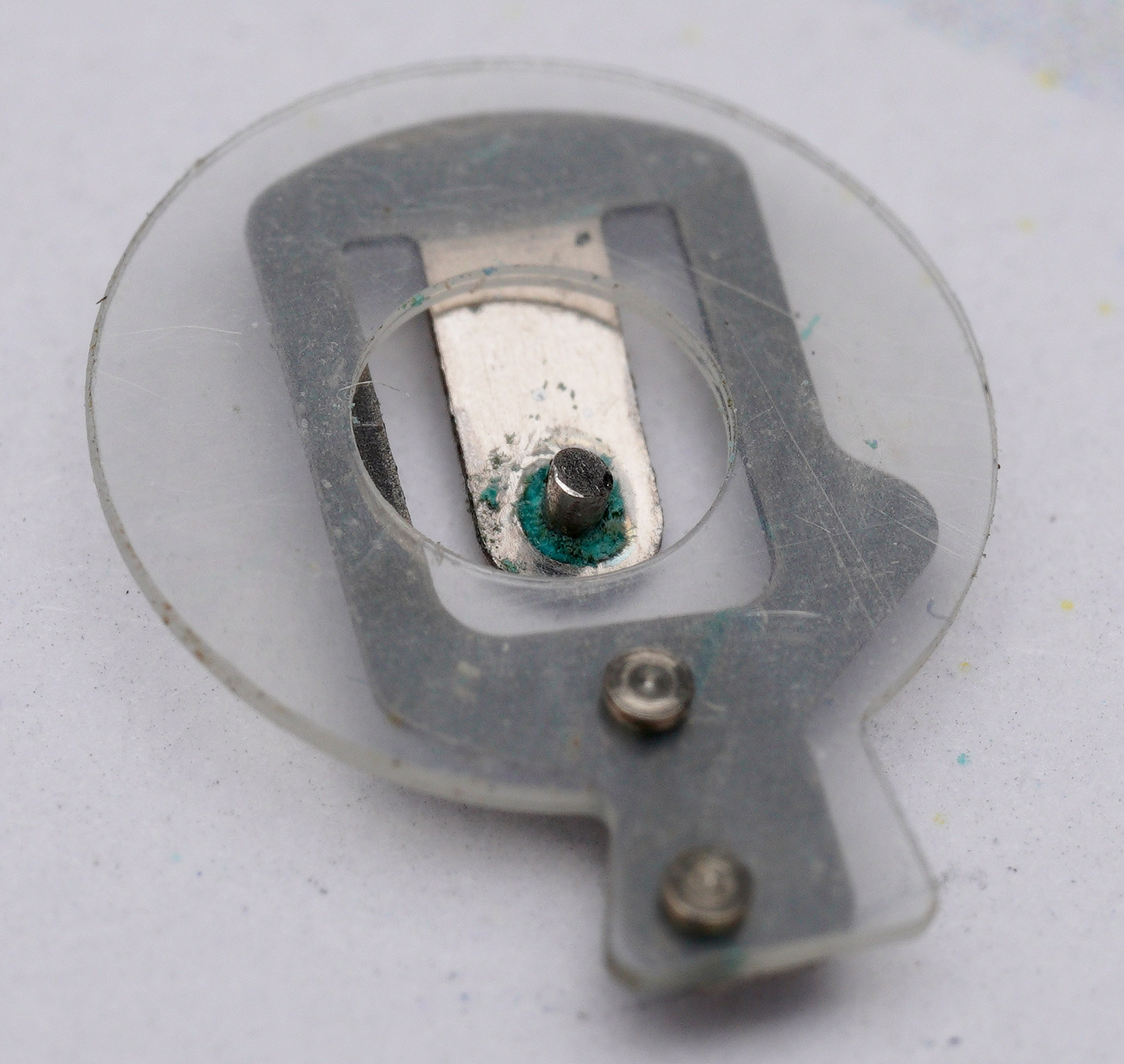
The solution to the second was to fashion a circular insulator to prevent the terminal shorting to the body of the main plate.
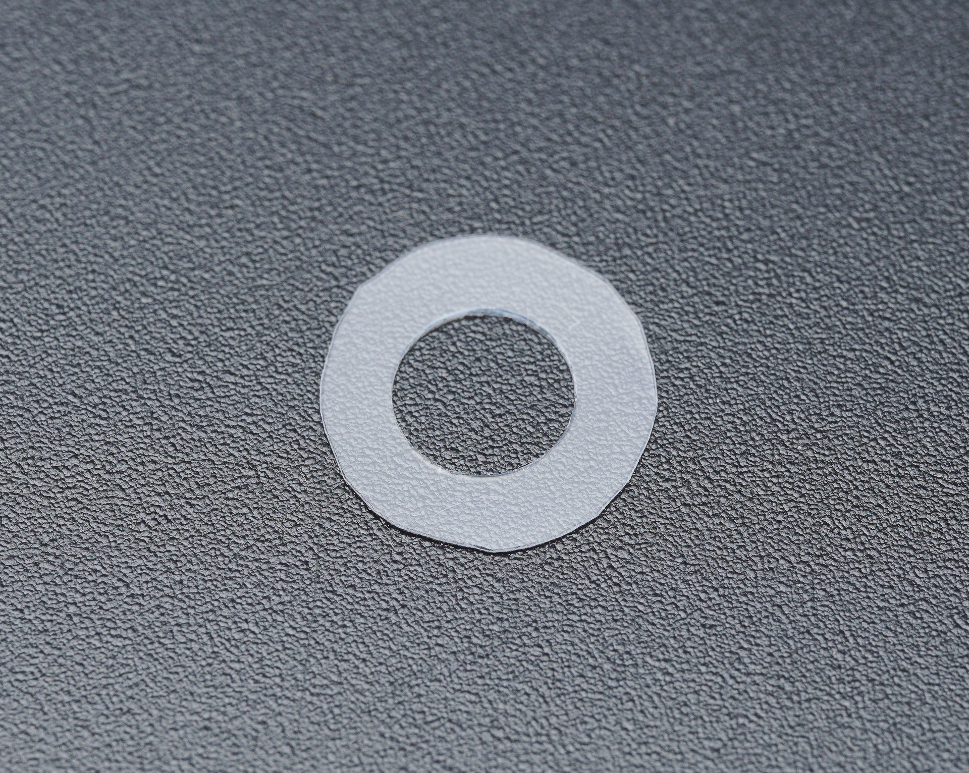
Here it is in position.

The proof of the pudding is in the eating. Here is the modified 344 battery, sitting on its insulating disk, the battery clamp secured, and the movement running.

I was curious to see what my timegrapher was reporting, having had difficulty getting it to work properly with one of my Seiko electronic balance movements. No such trouble here:
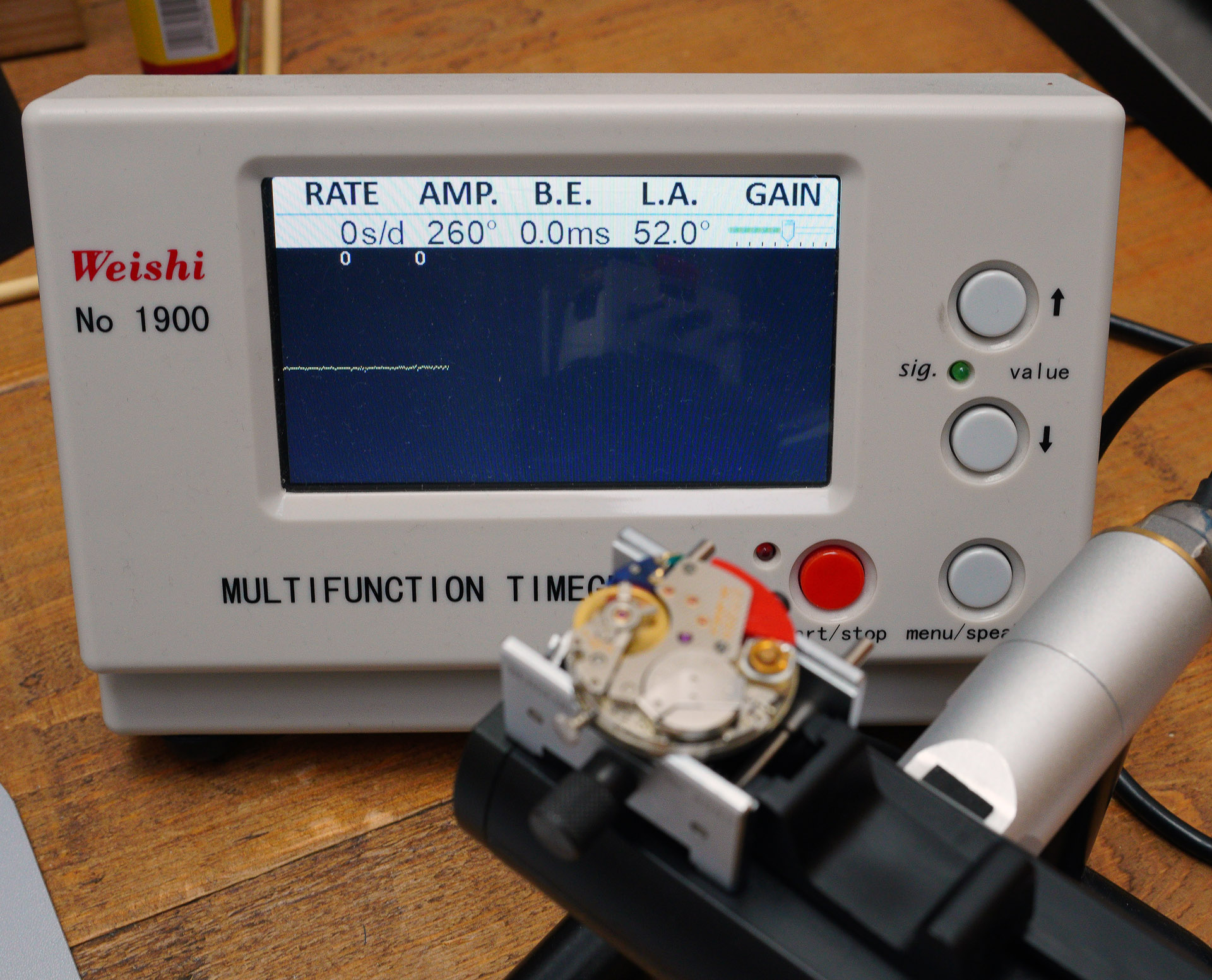
Initially, I was achieving about 235 degrees of amplitude, but a tweak to the amplitude controller quickly saw this increase to around 260 degrees, which seemed healthy enough.

The timing graph displayed above is obviously the result of some regulation, rather than the out-of-the-box result. The fly in the ointment was that upon inverting the movement, it would stop. The reason for this was that the coil was not positioned perfectly at the mid-point of the two tiers of the balance wheel and the little bit of end-shake in the balance staff caused the magnets to get too close to the coil with the watch oriented dial-side up. The solution was simple: removing one of the two shims sorted the problem. I felt confident enough in the performance of the movement to refit the hands with a view to reuniting the interior components with the exterior.

The eagle-eyed among you may note that I did a better job polishing away the tarnish on the minute hand than I did on the hour hand. That is a little job for the future when I have a spare moment.
One of the important last tasks is to fit a new crystal to the cleaned mid-case.

A fresh gasket fitted to the crown and the movement can be reunited with the case.
The strap that I’ve fitted to the case is a simple black leather lizard print that suits the watch very well.
This is one of those projects that took rather longer to complete than I expected but not because of some major headache mid-way through but because of an imponderable at the death. I could find nothing really online that reported similar battery-compatibility issues but I wonder whether that might be because the battery terminal prong on mine seems to have a profile to it that I’ve not seen in other photographs of the part. Whatever the reason, my watch is working and runs with an extremely impressive appetite to keep excellent time.

This watch is important for at least two reasons: arguably it was the world’s first transistorised electronic balance-driven watch; and it marked the beginning of Citizen’s transition from one of the largest manufacturers of mechanical wristwatches in the world to one of the largest manufacturers of quartz watches. The path it took from the one to the other was somewhat more circuitous than Seiko’s, but this watch represented the nucleation point. As to whether being the first transitorised electronic balance watch is important is open to question. This technology was doomed from the outset but it is a fascinating branch of horology to which it is worth bearing witness.
* Thanks to Gerald Donovan and other commentators in the comments here and on my Instagram feed for pointing out that I had initially got the manufacture date wrong for this example. Rather than being a very late example (I’d assumed 1971), the case serial number actually dates the watch to December 1965. One commentator suggests that the transition from Electric to Electronic may have happened as early as 1966 in which case the movement and dial of my watch may well be original. If the transition occured much later than 1966, then it may be that this watch has had a movement and/or dial swap at some point in its history. However, I have seen at least one other photograph online of a late 1965 watch with pre-Cosmotron X8 Electronic branding on the dial and Citizen Electric Watch on the caseback – identical to mine – and which provides at least some corroborating evidence that all of the components of my watch may be original to this watch. If anyone can offer further information, please do so in the comments.

Citizen serial numbers are –
First digit: final digit of the year. Second and third digits: month.
Your watch is from December 1965 🙂
I must have assumed that because this is an 0802 rather than 0801 that it was a late example rather than early. If it is December 1965 then that precedes the received wisdom for when these first appeared. I will perform some judicious editing in due source to reflect your corrections! Thank you.
I have an “Electric Watch” version from November 1965, suggesting that Nov/Dec was the changeover month for “Electric” to “Electronic”.
Thank you! All very useful information. I’ll update the article later today.
Great article as usual Martin! As you’ve said, there’s very little technical information about these movements in general circulation, so it’s great to see one from the inside.
I’m curious what your plan is for the future with regards to batteries – I was under the impression that these electromechanical movements eat batteries. Soldering on extra material to the battery each time the previous one dies sounds like a hassle. Have you considered a conductive spacer to extend the negative side’s reach? Perhaps something that could be trapped between the battery and insulating spacer. Or is the solder solution easy enough to do that that will be the long term plan?
Thanks Steve. I was just improvising a solution to this particular problem, but recognise that it’s not a long term fix. I will keep my eye out for a replacement terminal because I think that is part of the problem but your suggestion is a sensible one. I’ll be giving it some thought.
Great article, and the first ever to go into such detail with regards to this movement. Many thanks for a great read. Ross
My pleasure!
A fascinating insight into an almost forgotten branch of horology. I can almost smell the 1960-70s electronics from here… 😉 Wonderful photos showing everything so clearly. Thanks for sharing this Martin.
A perfectly timed post Martin (timed…see what I did there) to relieve Boxing Day stress! I wonder if Yahoo Japan sellers see a little blip in sales when your articles are posted? I’ve already been on to Zenmarket and got 2 or 3 Cosmotron’s lined up to enliven those short January days. As always those Citizen designers of the 60’s and 70’s gave the electromechanical approach all their attention with some remarkable results as Sweephand’s article on the Cosmotron shows. Thanks for bringing this interesting diversion to our attention!
Every Citizen I’ve worked on so far has really impressed me. Sweephand’s site is an invaluable resource for information on vintage Citizen. Thank you!
Great writeup. Thank you for sharing your work and your watch.
I’ve become a bit obsessed with the Cosmotron/X8 series, although they have got a lot more expensive recently. I’d love to get my hands on the titanium cased version but doubt one will come up.
I’ve got 3 of the early edition X8s, I believe the really early models all have the Citizen dial script in an italic font with ‘electric watch’ directly under the Citizen script or alternatively ‘Electronic’ is above the X8 logo on the dial. All of these feature the italic Citizen script.
The 7803 series of this movement are nice to work on as it’s drifted away from the shims found in the earlier movements (08xx or 48xx) and is much more solid state with no wires to connect. The date and day quickset is quite unique being a pusher driving the mechanisms depending on the position of the watch.
Happy to send some images over of the various dial types if you would like them and think I have some parts info albeit in Japanese.
Hi Yan,
Many thanks for your comment and information on the dial layout of the earliest watches. I wonder at what point in the production did Citizen switch from italic to upright font?
If you would like to send some photos of example dial with production dates (case back photos) then please do feel free to send me an email at amateurwatchfettler@gmail.com
Thanks!
Hi. This is a very interesting article. It solves the mystery of my Citizen x8, which is identical to yours – same dial, same back cover and s/n 51100xxx. This means that these watches must have been manufactured at the end of 1965. I also thought mine was made of several pieces, but I guess not! I bought a broken watch and replaced the electronics – the transistor was broken. You can see my watch and repair on Instagram – przemekwatches account. Regards.
I’ve seen at least one other example of identical apparent mismatches of dial/case/serial number and yours adds to the body of evidence suggesting that yes these watches were late 1965.
Hi Martin.
I have a question about the 7083A mechanism I have. I realize there is a different mechanism here, but I’ll try.
Currently, my watch has a speed difference of about 2-5 seconds per day. The watch service where I recently had it set says it’s a very good result. I understand that the production time result may not be achievable. But are these 2-5 seconds per day really an acceptable result for this watch?
Hi Kamil,
The main benefit of a battery-powered balance-driven movement is that you should not experience the same fluctuation in amplitude with power reserve as happens with a mechanical watch. A hand-wound movement wound once per 24 hours will see a much greater fluctuation in power reserve than an automatic movement but even the latter will be at the mercy of how active its wearer is during the day. In an electronic balance-driven movement, the battery should supply a consistent impulse to the balance for as long as it is in a good state of health and so should deliver more consistent amplitude and hence time-keeping over the course of each 24 hour period. In other respects though, an electronic balance-driven movement is subject to the same positional variation as a mechanical movement and will be subject to the same stresses to the gear train as a wholly mechanical movement and so an accuracy of 2 to 5 seconds per day would seem reasonable in a watch that has not been very finely regulated.
I hope that helps
All the best
Martin
Thank you very much for your reply.
This clears up the whole situation for me. It turns out that even a sudden movement of the watch can cause differences in time.
Is the battery in this watch with a voltage of approximately 1.23 V suitable for replacement?
Additionally, I have a problem finding the back gasket. Would you have any advice on what to use for the 4-791002K watch?
All the Best
Hi Kamil,
The original battery would have been 1.55 V I think and so I would recommend using a modern equivalent. As for the rear gasket, my approach when I don’t have a part number is just to take measurements and then buy a few generic gaskets either side of what I’ve measured. Trial and error inevitably costs more I’m afraid!
Hi Martin, I’ve just purchased an X8, model number 4-810015y , still tagged on the strap and gold plastic on the case back , said it ran for 3 seconds then stops, saw a pic of the movement, can’t be too bad I thought. In one of the the pics the plastic -ve spacer is clearly visible, it rocked up without it. I’ve cut the plastic the battery came in, inserted a screw so it touches the arm underneath and leant the battery on top on the scunt and it’s working, can’t get it to work in position under the clamp though. My questions are, do you know the movement number of my model so I can search on Emmy? Do you happen to know the part number of the one in your pic, design and style look the same as mine? Any models you’ve come across that may use something similar and lastly seeing as you had similar battery issues if yours were missing the spacer/contact, other than sourcing a replacement, how would you try to rig up a makeshift jobby?
Thanks for any help, kind regards…Steve
Hi Steve,
I went through this process with my X8 and I may be able to offer some help nights but I’d need to have a dig back into my notes and take a look at the various parts watches I bought to resolve my problem. I will try to reply tomorrow with more information.
Hi Martin, much appreciated. After some research my movement is maybe 0840/0880 it’s a 1970 with transistorized on the dial , 12jewel.
Kind Regards….Steve