
Tags
The mechanical chronograph is arguably the most anachronistic variation on the theme of the mechanical wristwatch and yet it evokes powerfully a time when chronographs were associated with fields as diverse as racing (in all its sporting variation), aviation, astronomical observation and space exploration. Some of the most iconic wristwatches of the 20th century are chronographs yet in spite of these glamorous associations, their chronographic functions are now more likely to be limited to the occasional timing of the boiling an egg or simply to provide a tactile diversion in idle moments.
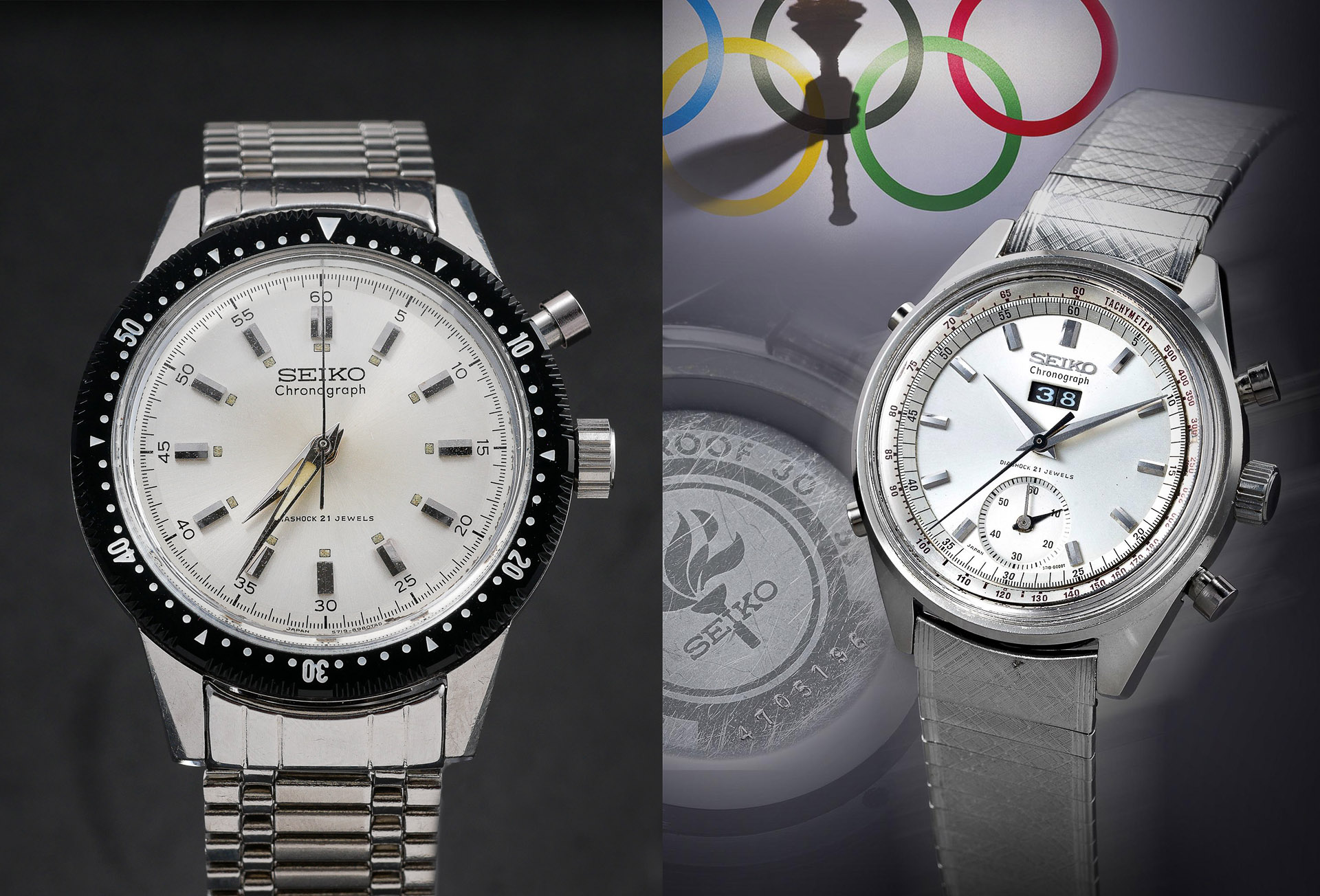
Seiko’s historical development of the mechanical chronograph is important in terms of technical innovation and achievement but also in terms of its diversity when compared to the output of many other contemporary watchmakers. Their earliest chronograph was the hand-wind Seiko 5719 Crown one-button chronograph released to coincide with the 1964 Tokyo Olympics. A number of no-date and date variations were produced over the next year or two, including one very special limited-edition evolution, with elapsed minutes and running seconds and a manual point counter displayed in a window south of the 12 marker.
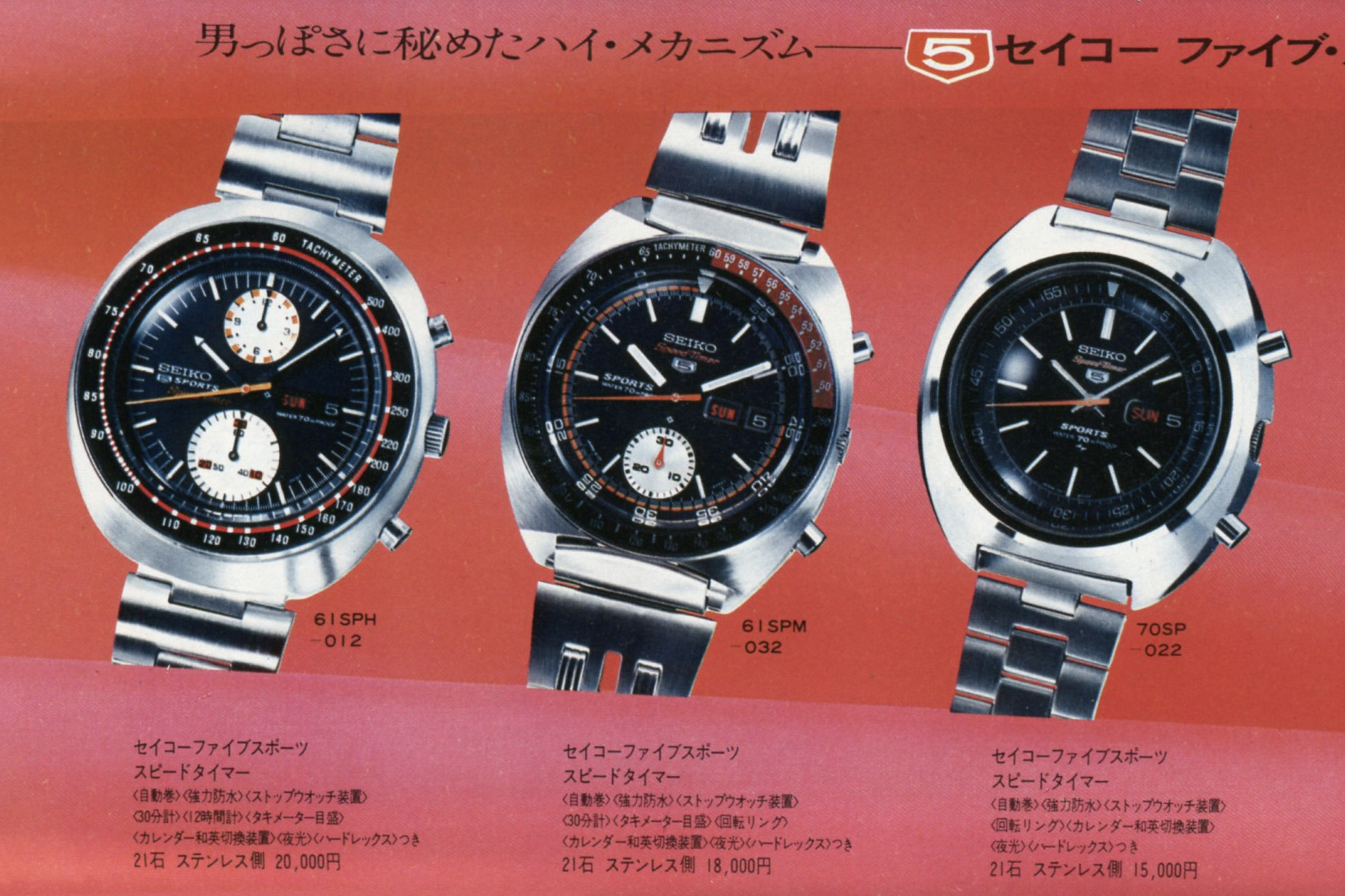
The next significant advance had to wait until 1969 with the announcement of the single- and double-register 6139 and 6138 automatic chronographs. The 61-series chronographs were 27mm in diameter but the substantial thickness of the movements (7.2mm for the 6139 and 8mm for the 6138) dictated that the watches to which they were fitted were generally quite generously proportioned. That is not necessarily a bad thing given the somewhat macho image associated with watches of this type, but there was always going to be a market for something a little more wieldy and subtle, and to that end the Daini Seikosha division of the company set about producing a chronograph of more discrete dimensions and which offered something absent in the 6139: a fly-back function.
The simplest of this new series of automatic chronographs was the 7017, produced from 1970, and featuring a seconds-only chronograph with a fly-back function, allowing the chronograph to be reset without first stopping the timer: stop, reset and restart could be accomplished with a single button push. This watch was celebrated at the time as the smallest automatic chronograph in the world, a marketing achievement that perhaps overshadowed the rather modest feature set. However, two further developments of this initial foray were to follow over the next two years: the 7018, which appeared in 1971, added a creeping elapsed minute hand in a sub-dial above the 6 position yet retained the same dimensions as the 7017.
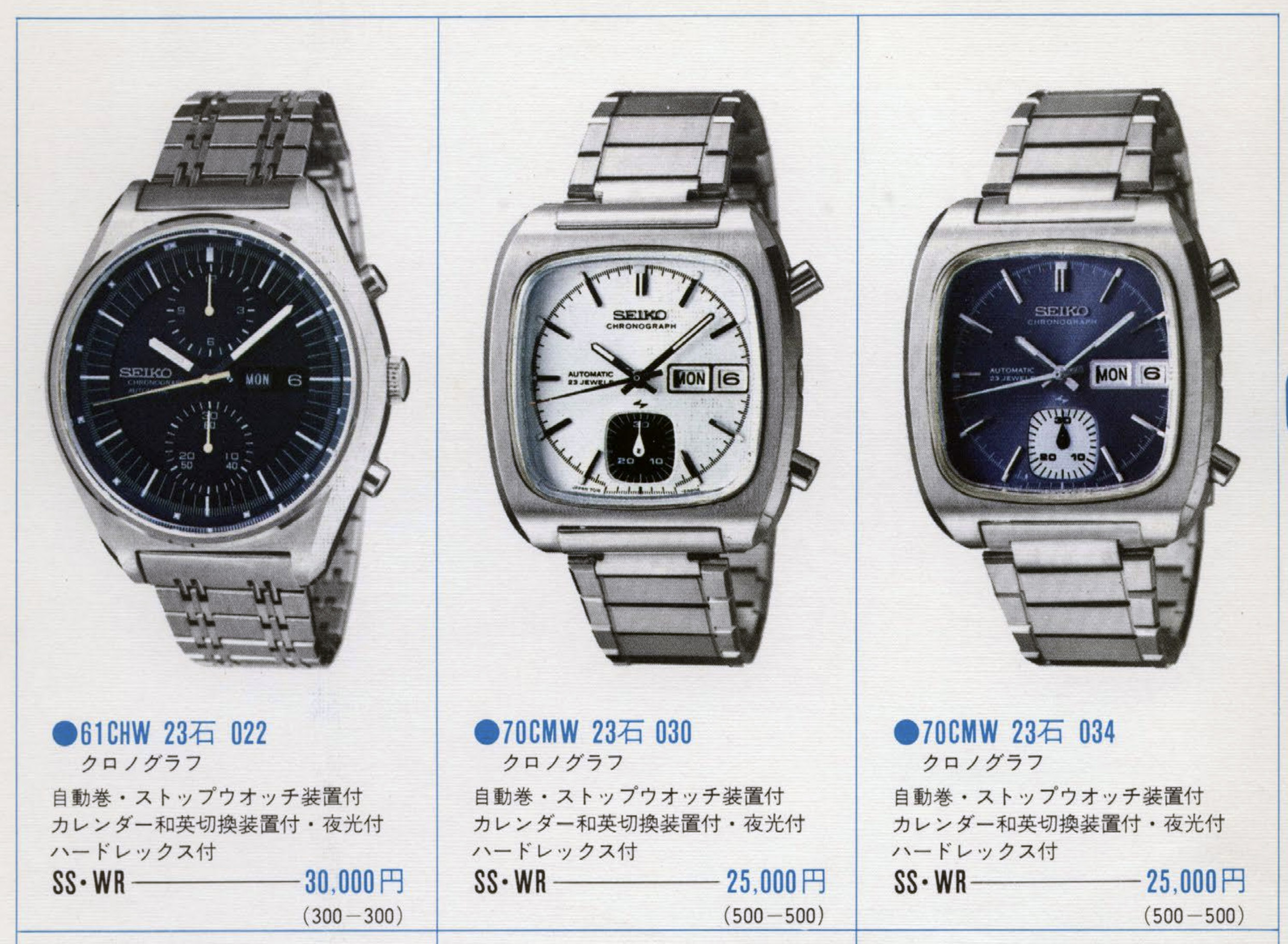
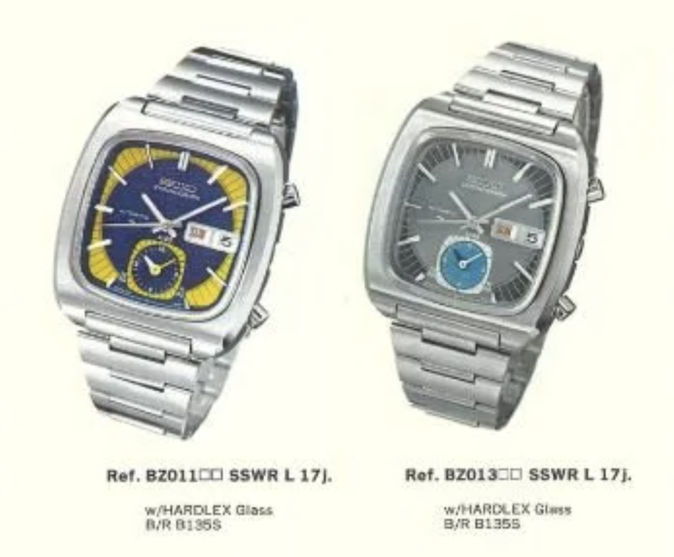
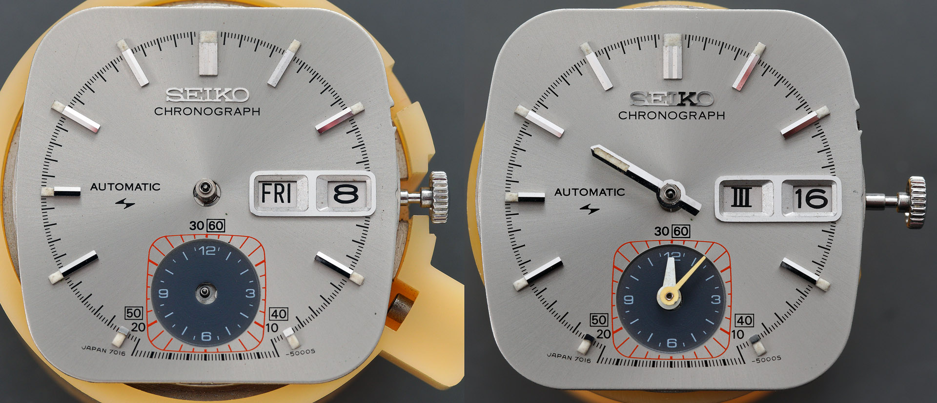
The 7018 first appeared in the Japan Domestic Market catalogue in 1972 but its presence in subsequent issues of JDM catalogues was low-key, and extended to far fewer model variations than the 7017. The model displayed in the catalogue shown above is the 7018-5000, its square case and dial inspired perhaps by the Heuer Monaco chronograph introduced a few years earlier. A year later in 1972, the 7015 and 7016 arrived, the former not seemingly offering anything beyond that of the 7017 but the 7016 offered something rather unique in providing a pair of concentrically-mounted hands within a sub-dial at the 6 position, one of which tallying elapsed minutes and the other, elapsed hours.
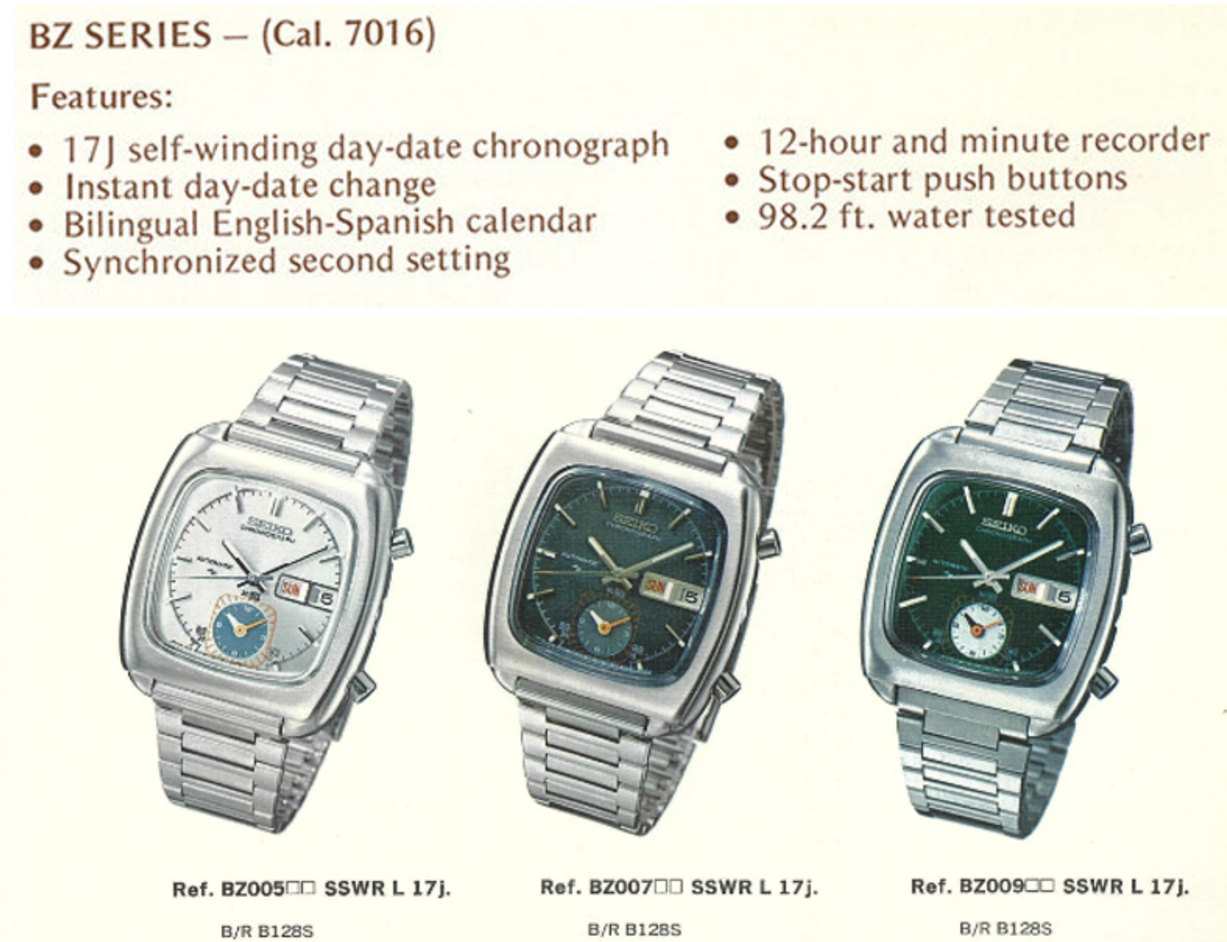
The 7016 seems not to have been widely available in the Japanese domestic market, being prioritised instead for the international market and so catalogue entries are rather more tricky to find. The three models shown in the English language catalogue image above are clearly design evolutions of the 7018-5000 ‘Monaco’ watches shown in the previous image. Superficially, they appear to be housed in the same case, and indeed retain the 5000 designation in their model number, but the earlier case lacks the delineation of the lugs in these later cases and has more clearly sculpted sides featuring alternating polished and brushed surfaces. Interestingly, a variation of the 7018-5000 case was used to house the 7016 but the model designation changed from 5000 to 5010.
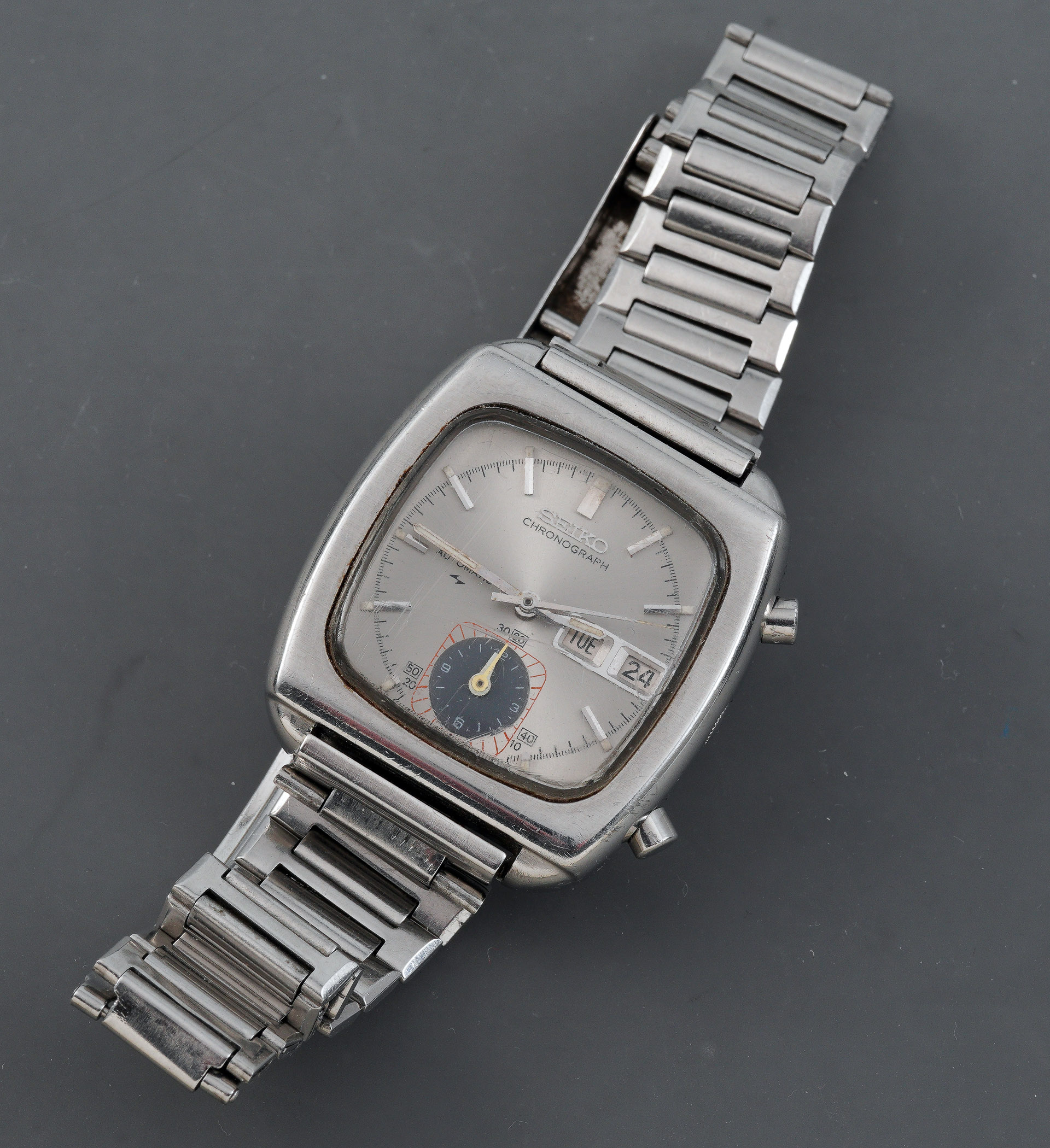
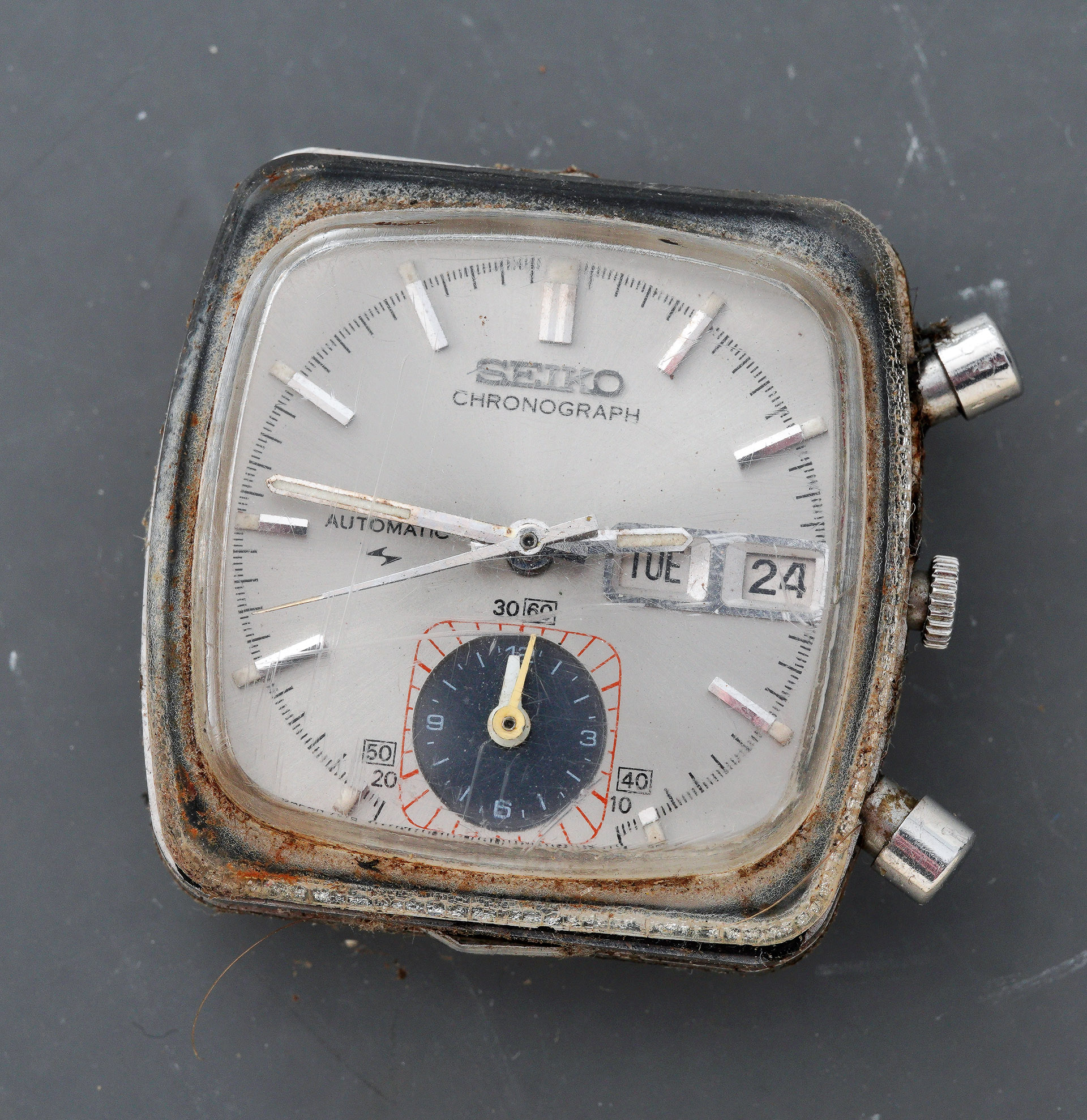
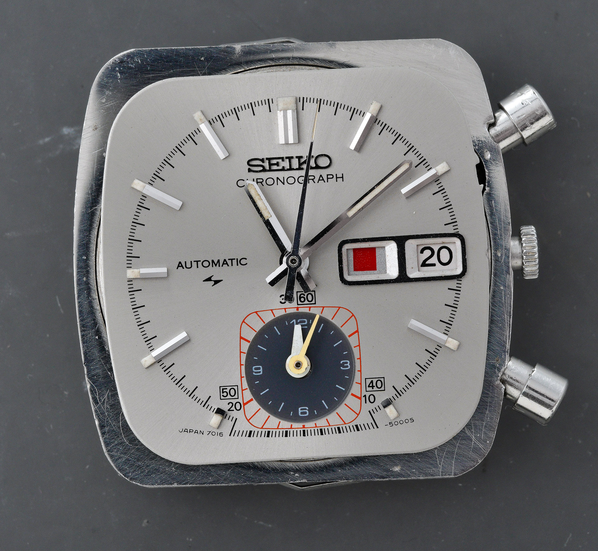
Now that I have you all thoroughly confused, I think it is time to introduce our subject. Unusually, almost without precedent in fact, our project today concerns a watch not owned by me but by a former colleague who asked me to perform a revival, to raise it from the dead. The watch is a Seiko 7016-5000 from September 1972, purchased new in 1974 by its current owner whilst working as a post-doctoral research fellow in Palo Alto near San Francisco.
The owner wore the watch most days from then until semi-retirement in 2016 by which point the autowinding mechanism had failed. A service in 2019 was supposed to have resolved the problems but the watch ground to a halt at some point between then and now and that’s where I come in.
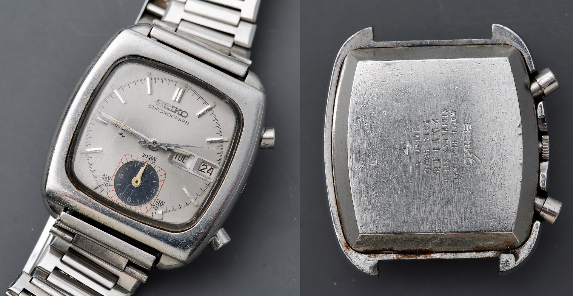
The watch is wholly original, still fitted to its original bracelet and bears scars typical of a well-worn, long-term everyday watch. The model and serial numbers inscribed on the case back are consistent with previously documented deductions1 about the history of this particular model: watches manufactured in 1972 were assigned the model number 7016-5000 whilst those manufactured from January 1973 became the 7016-5001. There are otherwise no distinguishing differences between the 1972 watches and those made from 1973 onwards. The association between model number and year of manufacture therefore suggests that the inclusion of the numeral ‘1’ at the end in the later watches has nothing to do with the destination market.
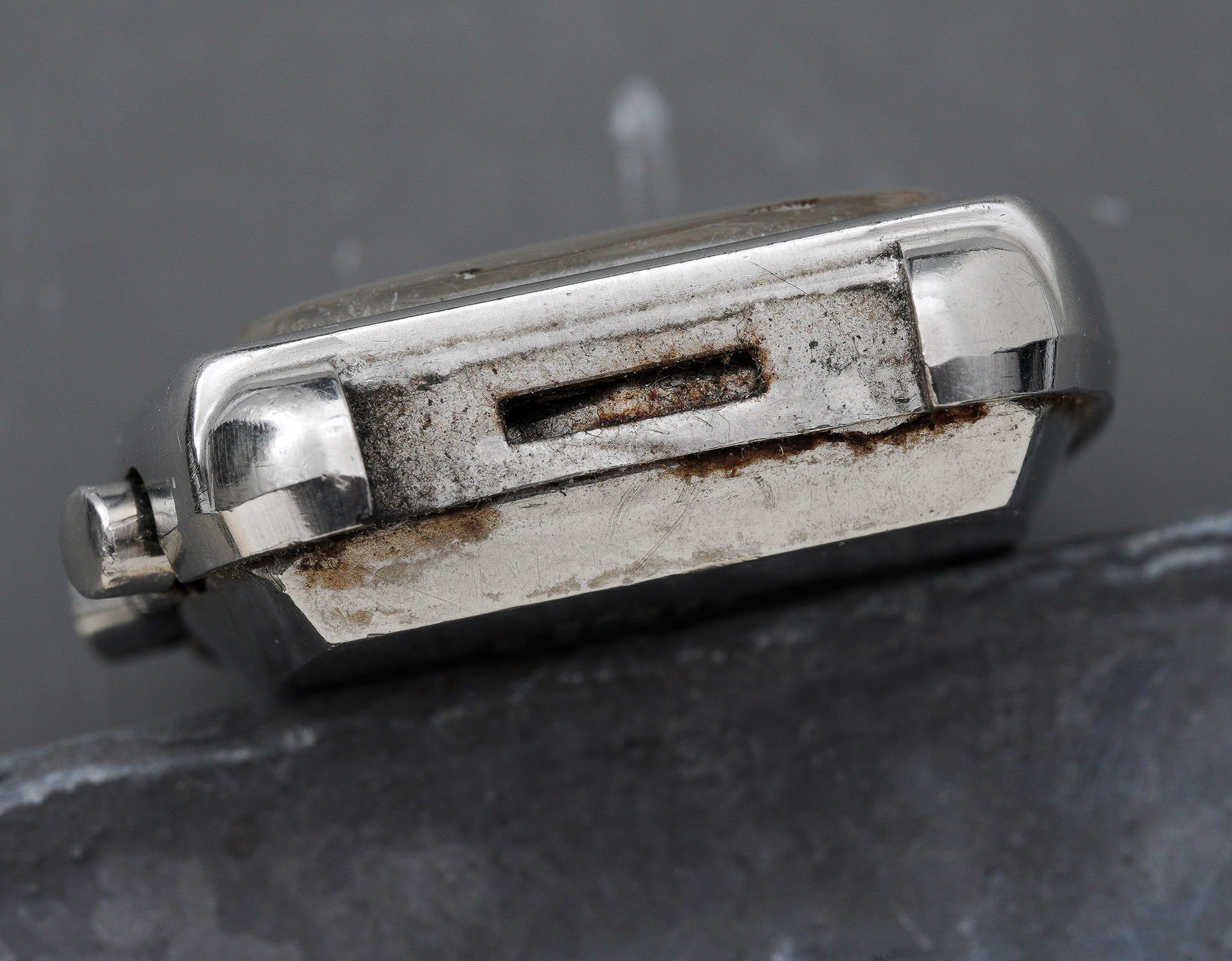
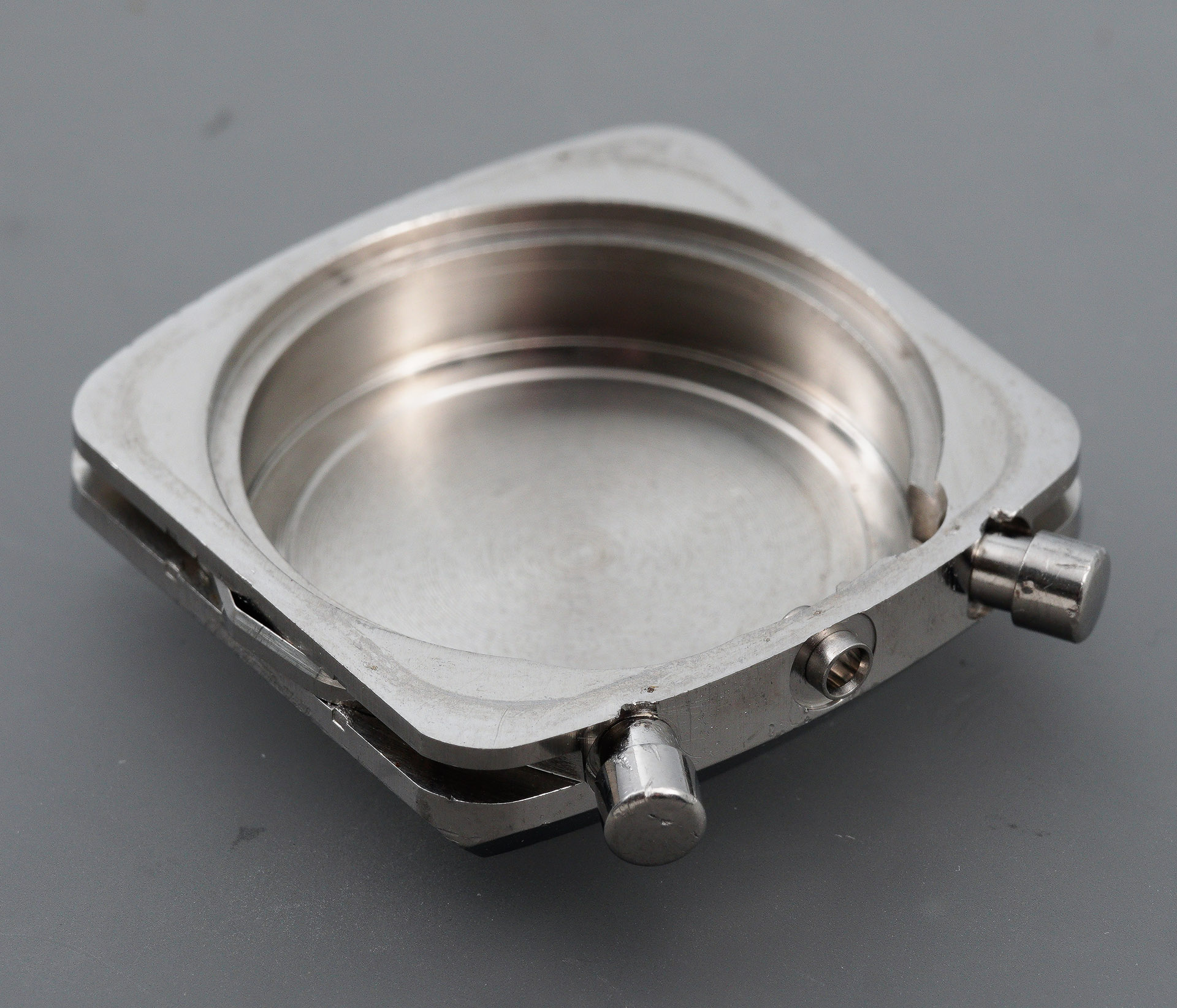
Before opening the watch up, I was able to confirm absolutely no signs of life. Not the slightest whimper. This being a square-cased watch, the construction is typical of that breed in having a two part compression design in which the watch movement is housed in a monocoque mid-case with the crystal seal secured by the force exerted by a separate upper case that fits over the top. Deconstruction of the case therefore needs a little foreknowledge of what is required to gain entry. We start by depressing each of the sprung tabs at the 6 and 12 positions whilst gently levering up the case.
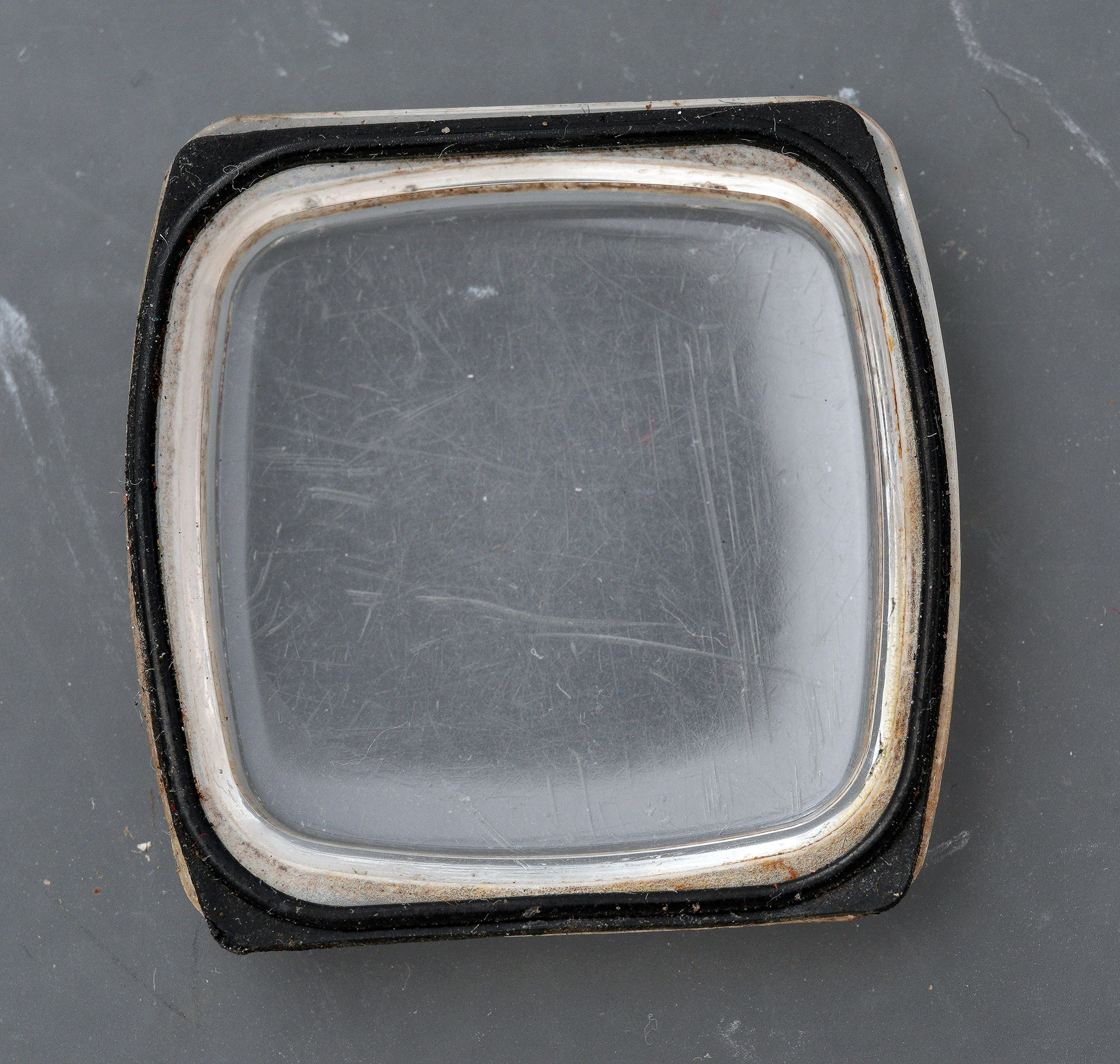
The removal of the upper case provides an unrestricted view of the construction of the mid-case and, in particular, the seating of the crystal and its gasket against the case.
The acrylic crystal is very worn and very dirty but not so opaque as to completely obscure the dial and handset. The crystal gasket is flat on the side that seats against the lower surface of the crystal and ridged on the side that seats against the flat upper surface of the mid-case.
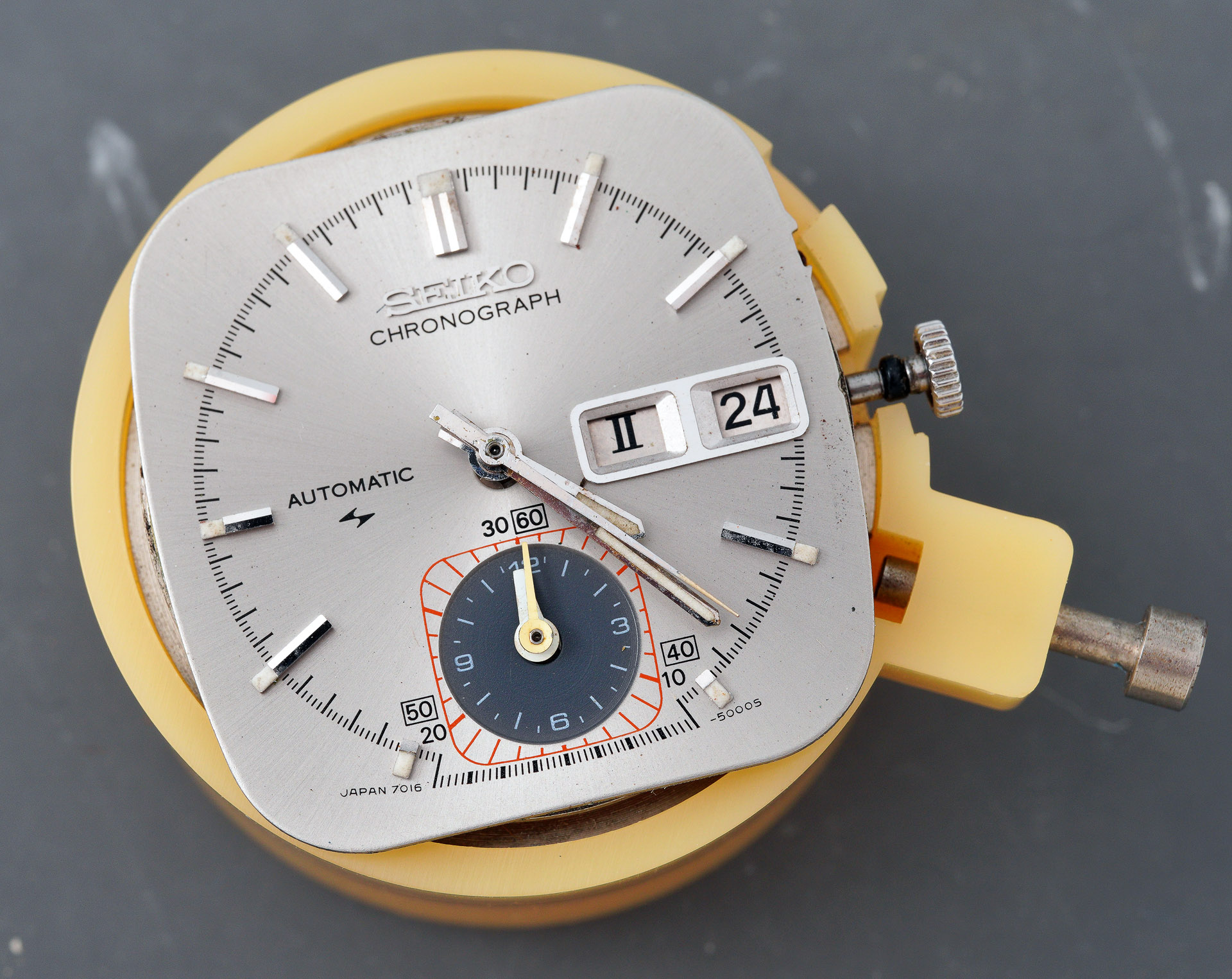
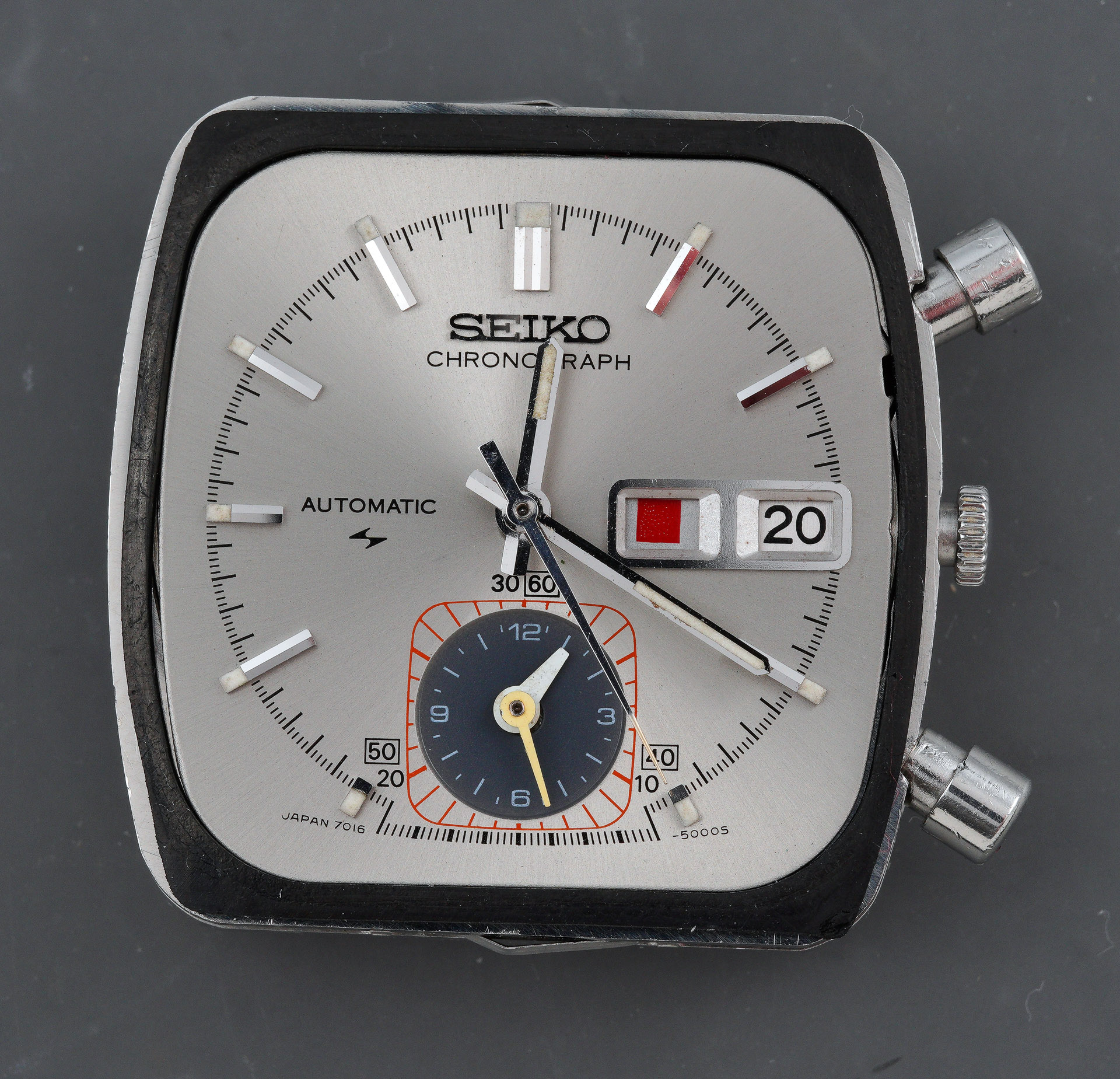
With the crystal removed, the dial and hands are exposed to unrestricted scrutiny.
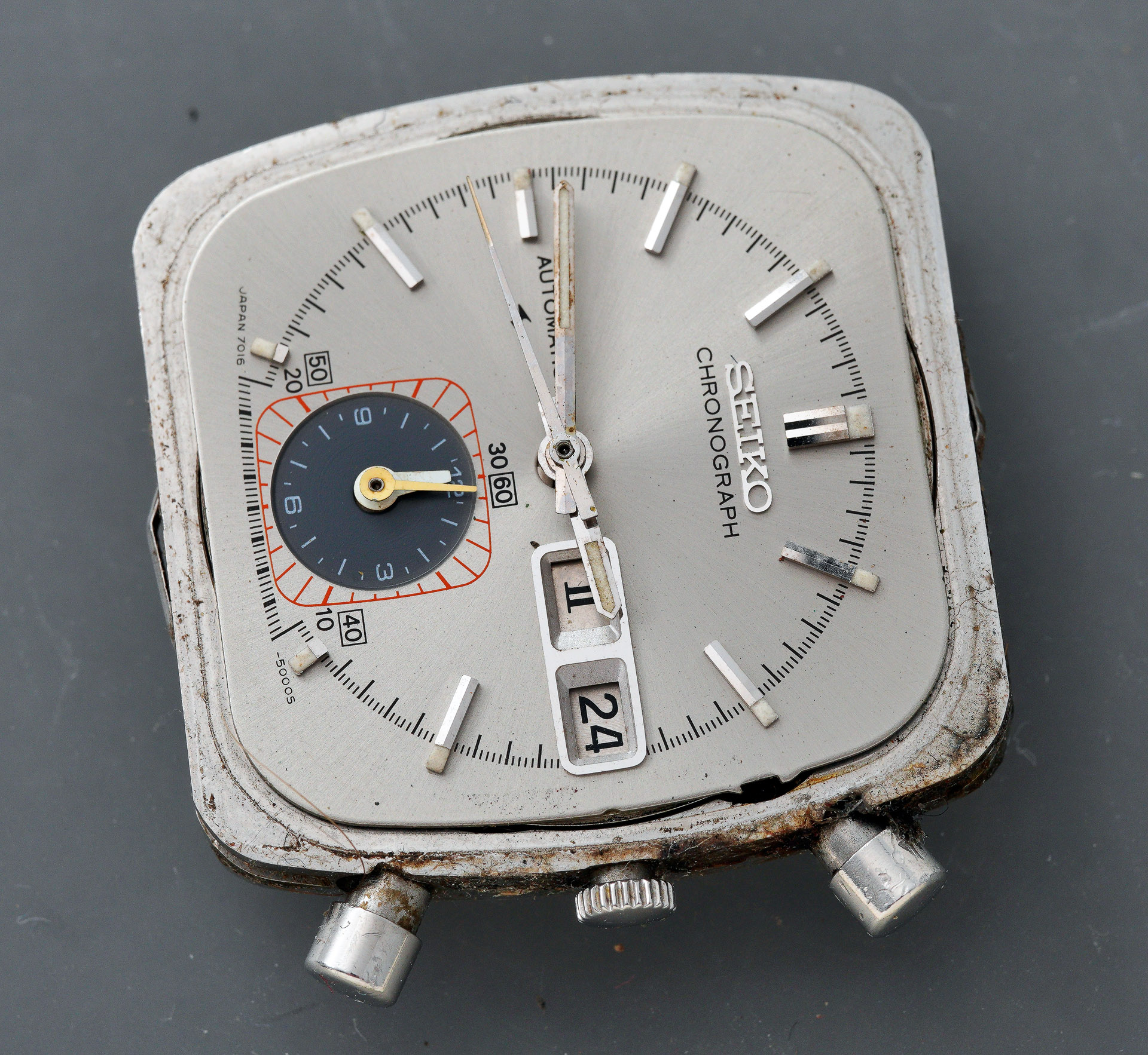
The dial itself looks to be in excellent condition, largely free from blemishes or signs of historic water ingress. The only notable flaw is a very minor beauty spot north-by-north-east of the 60 box on the sub-dial. The hands are less good however, the minute hand in particular showing signs of corrosion and minor discolouration to the lume. The two sub-dial hands show some signs of past watchmaker mistreatment.
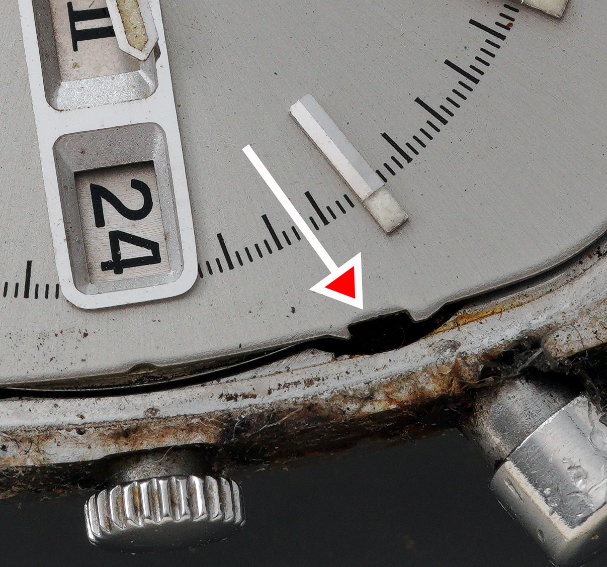
The next hurdle to overcome is to figure out how to remove the movement from the mid-case, the former being tied to the latter by the presence of the crown and stem, still in position. The crown release lever is operated by inserting a small screwdriver through the hole to the side of the dial near the upper of the two pushers.
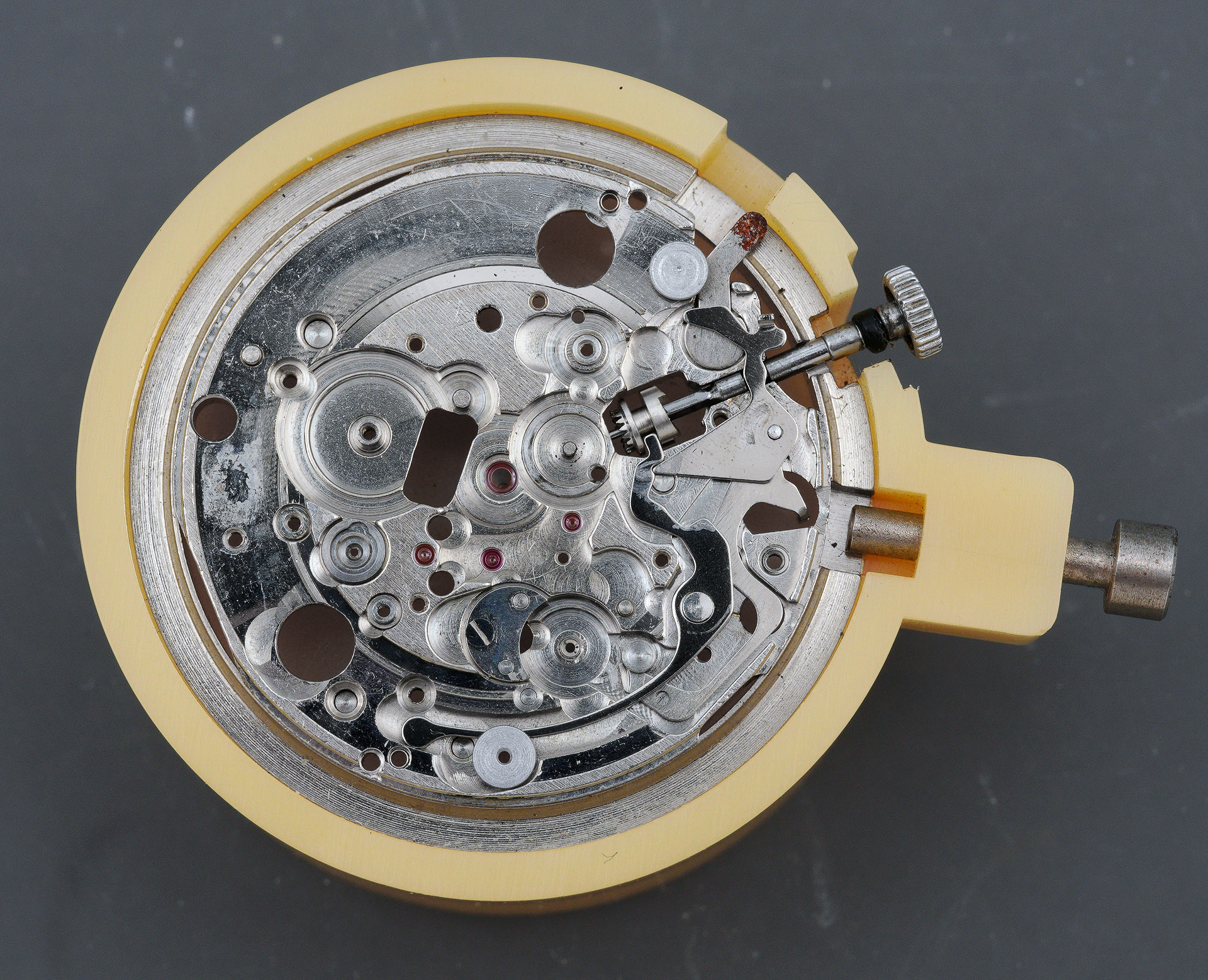
The crown and stem then slide out easily and we can tip out the movement at that point and take a look at its underside.
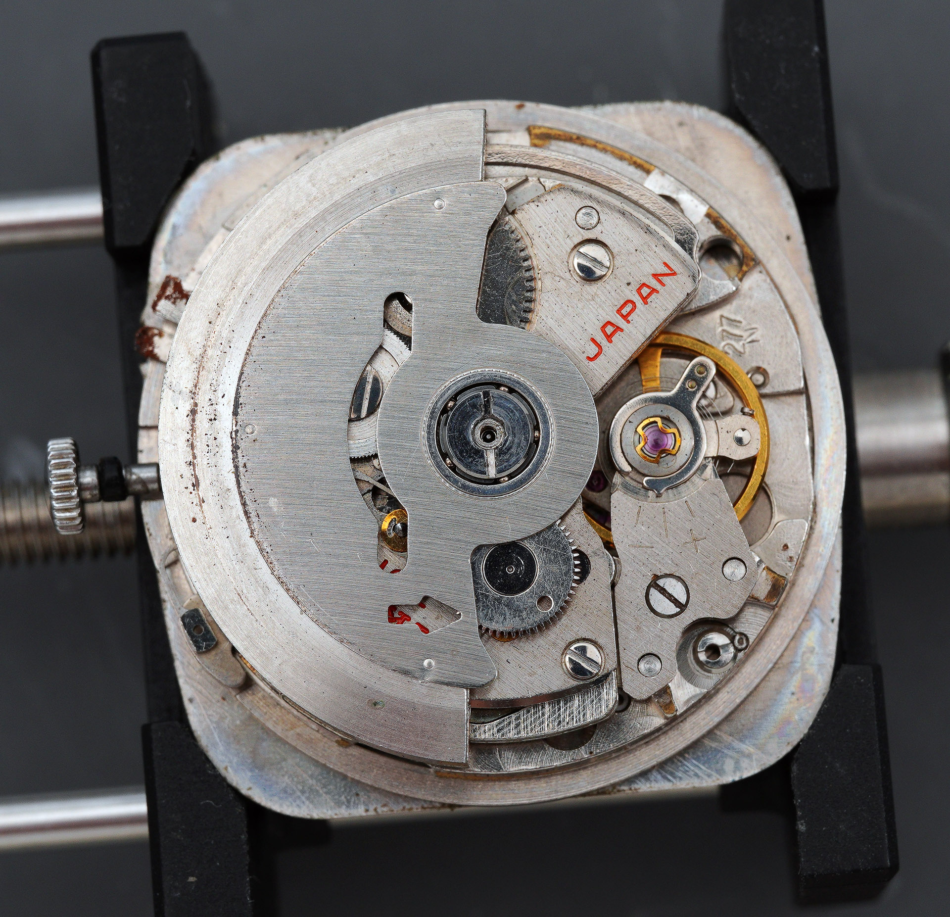
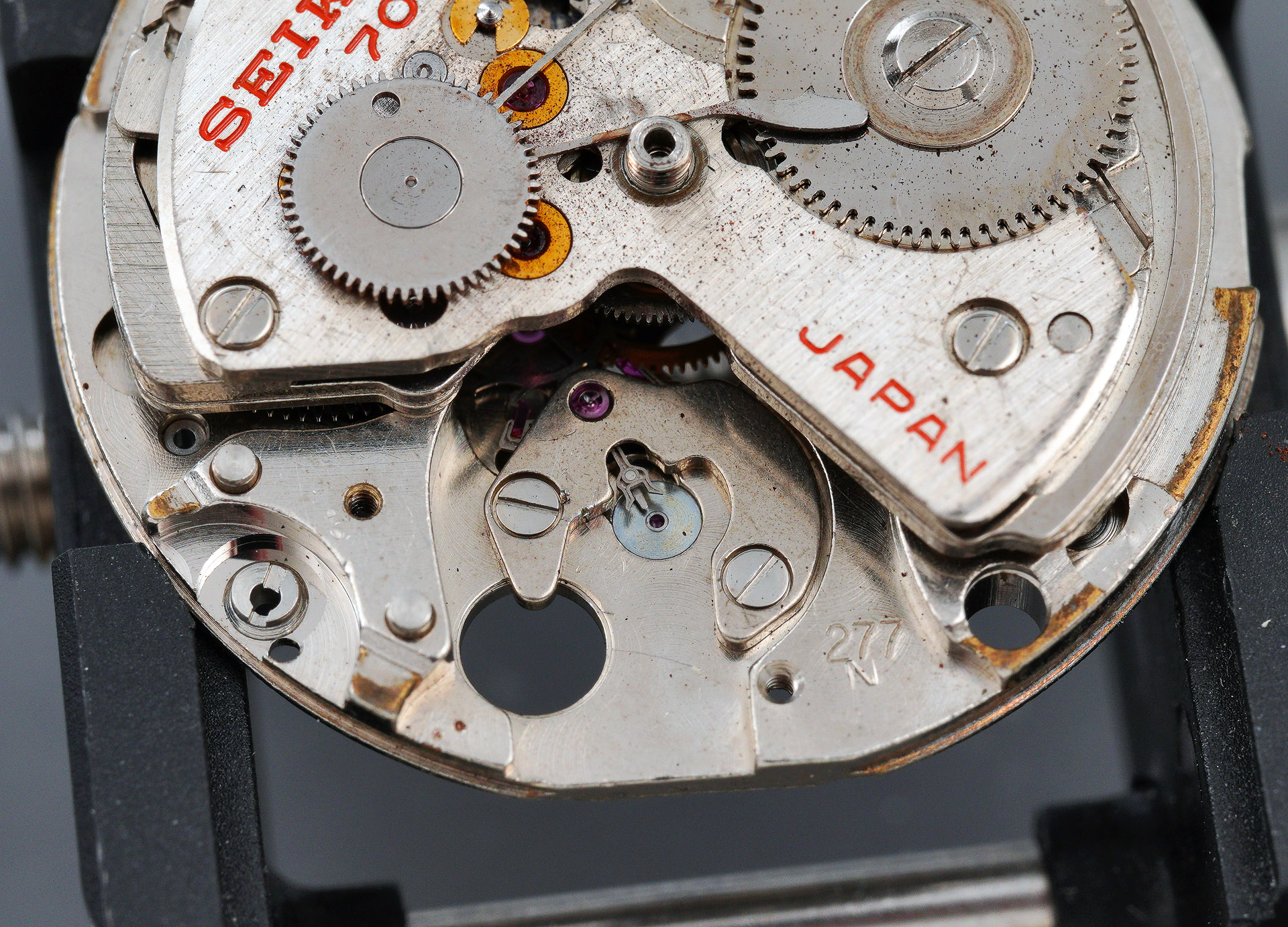
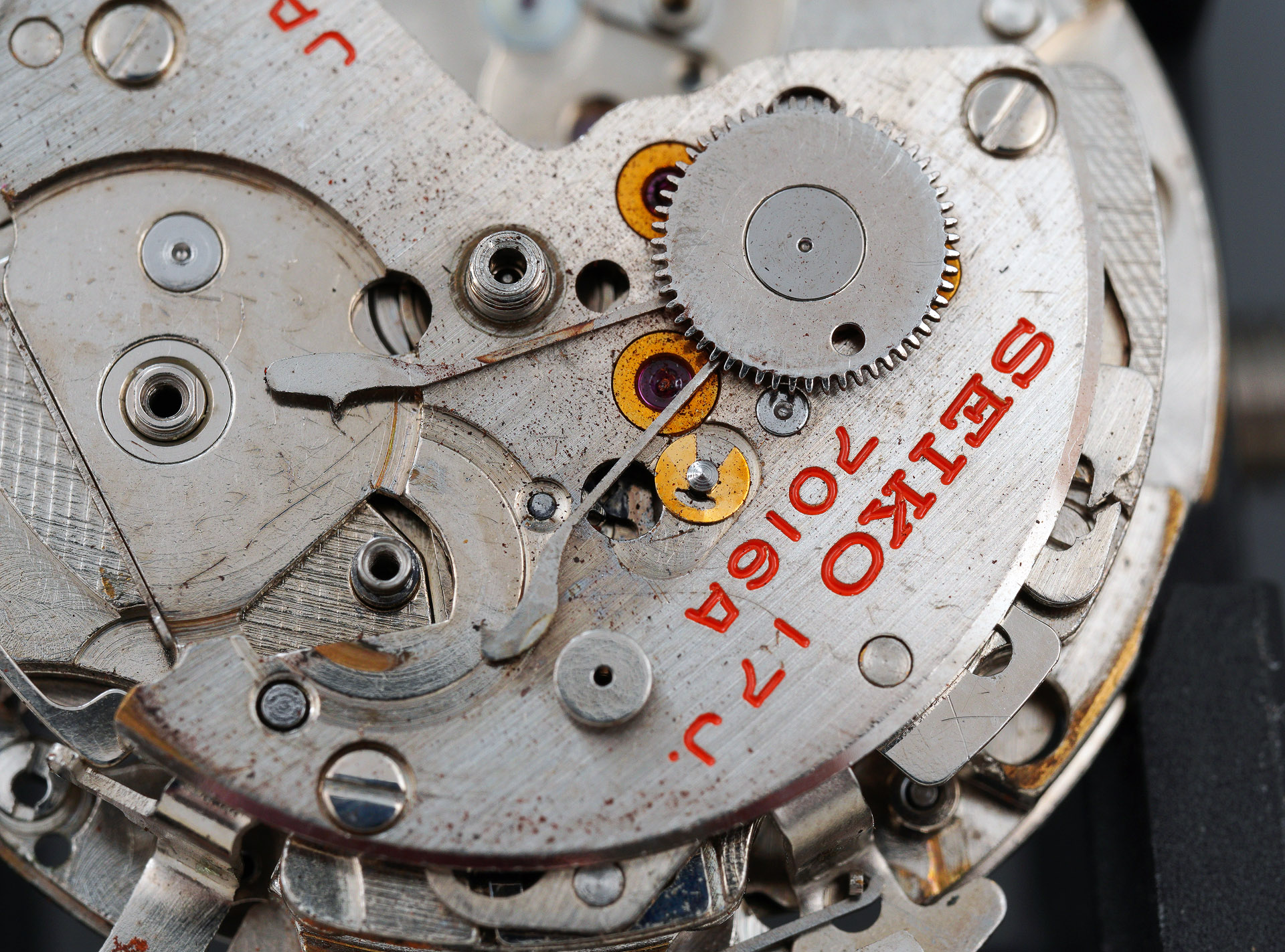
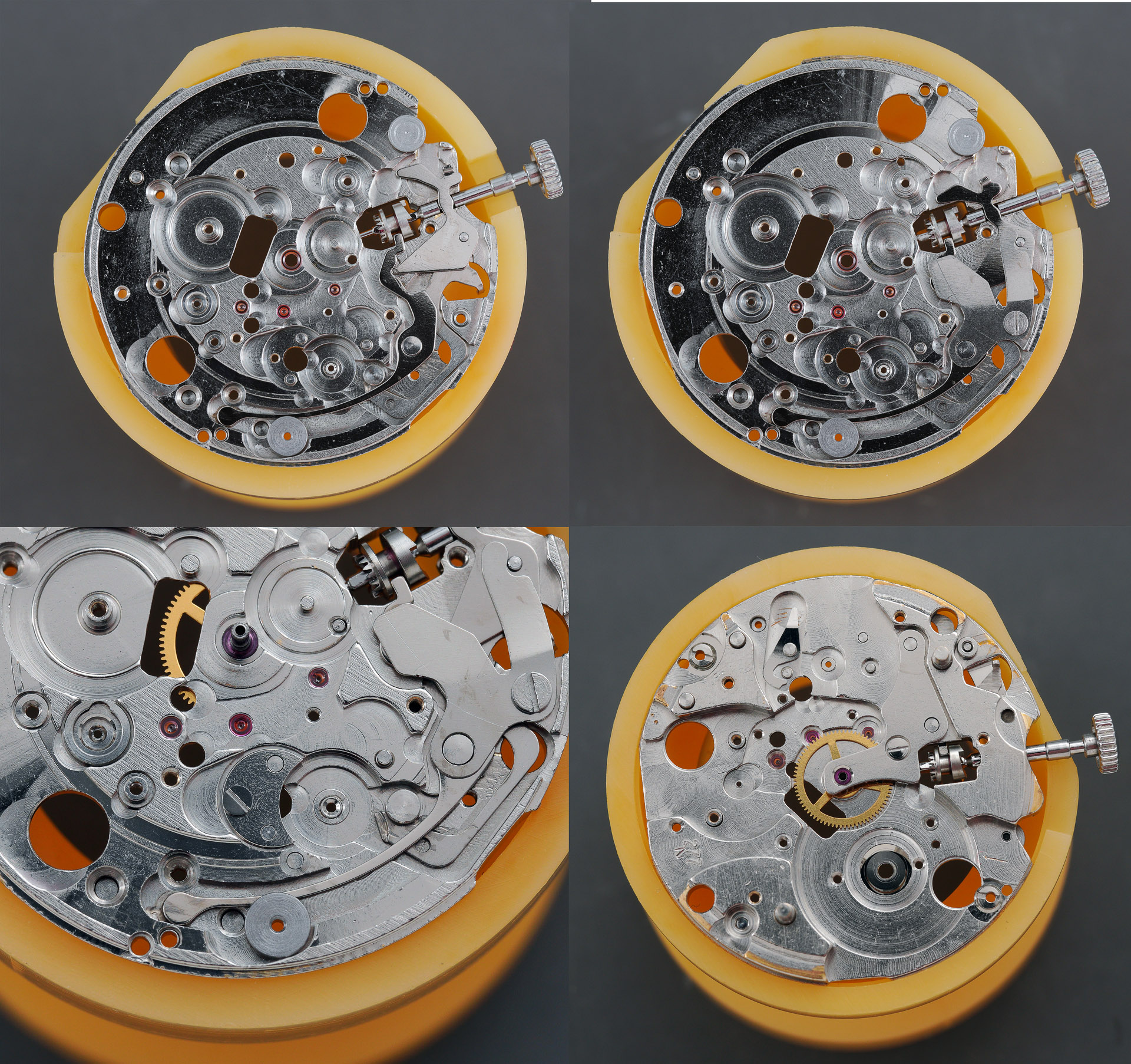
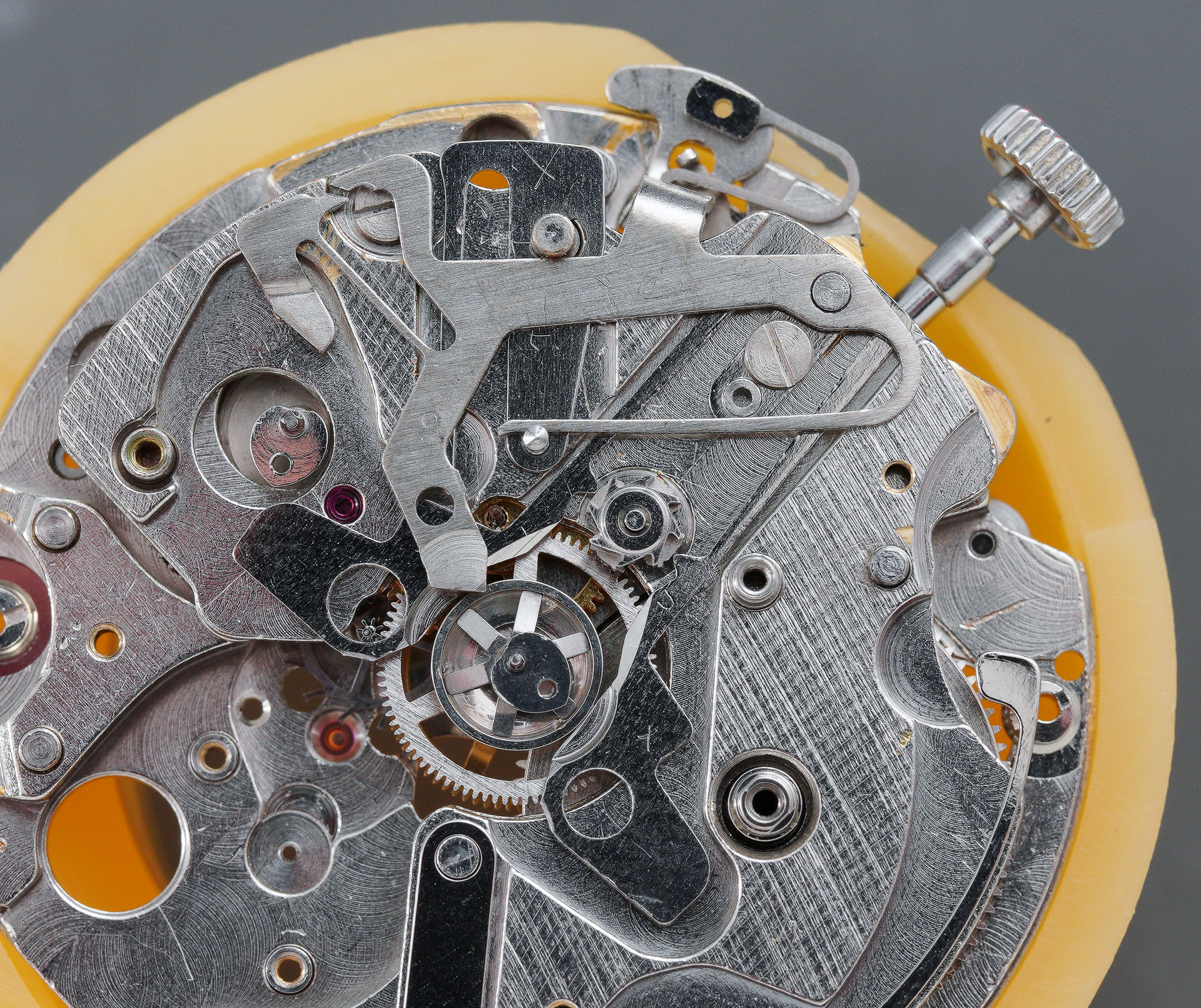
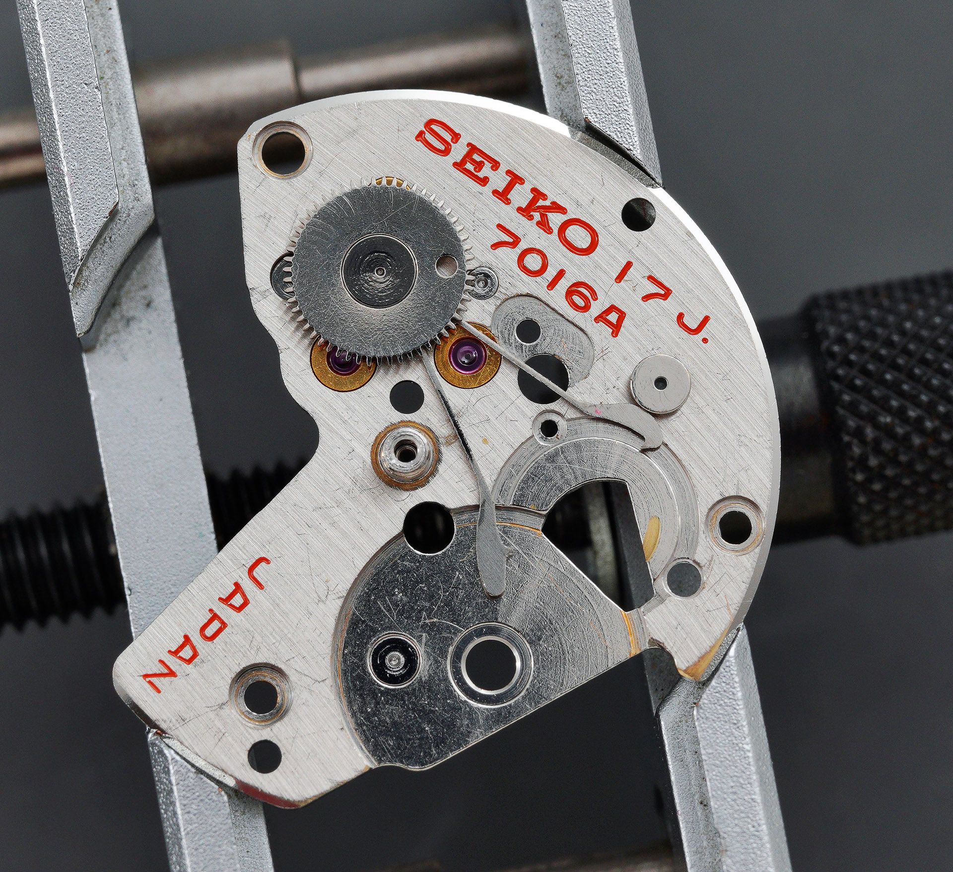
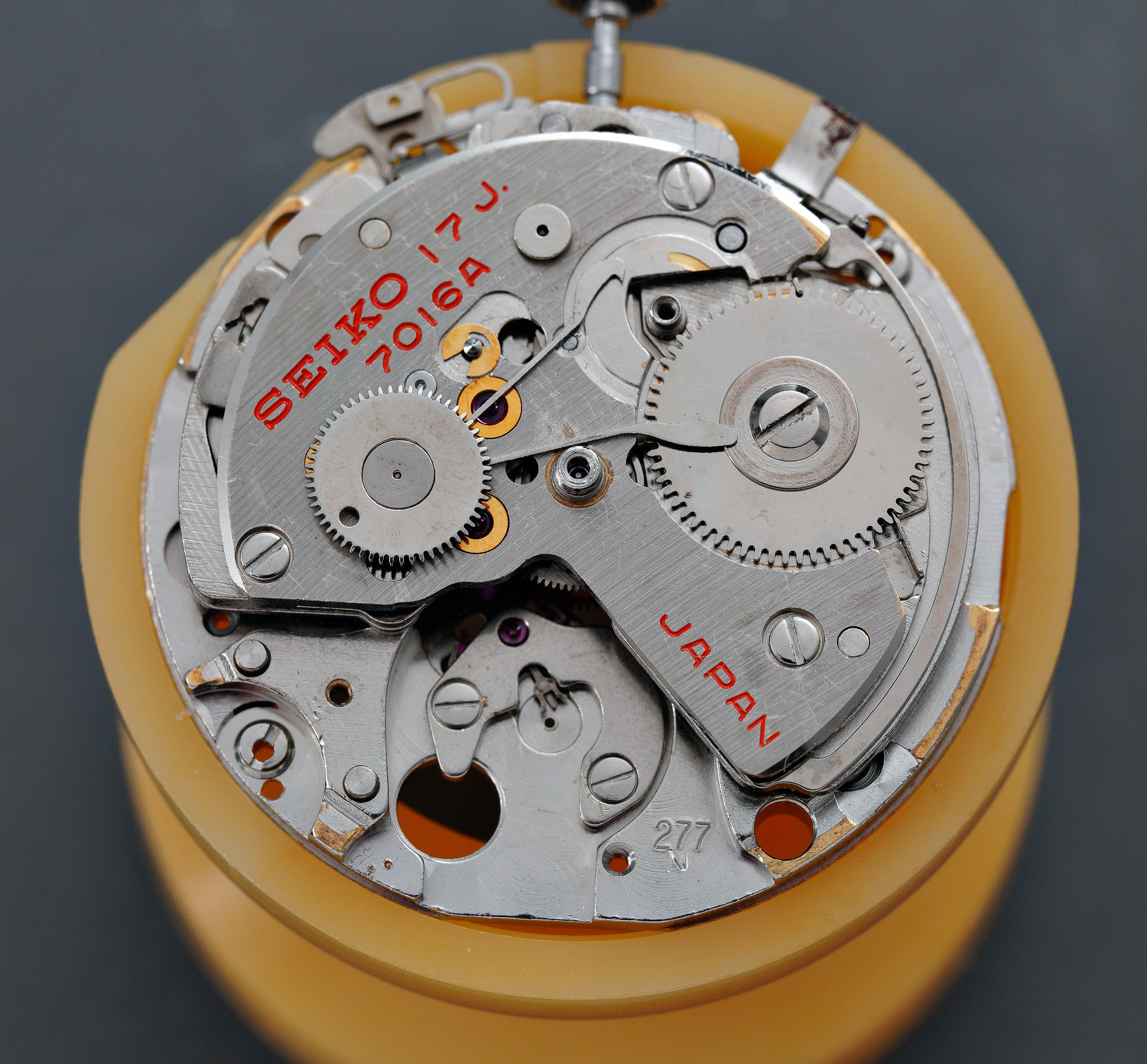
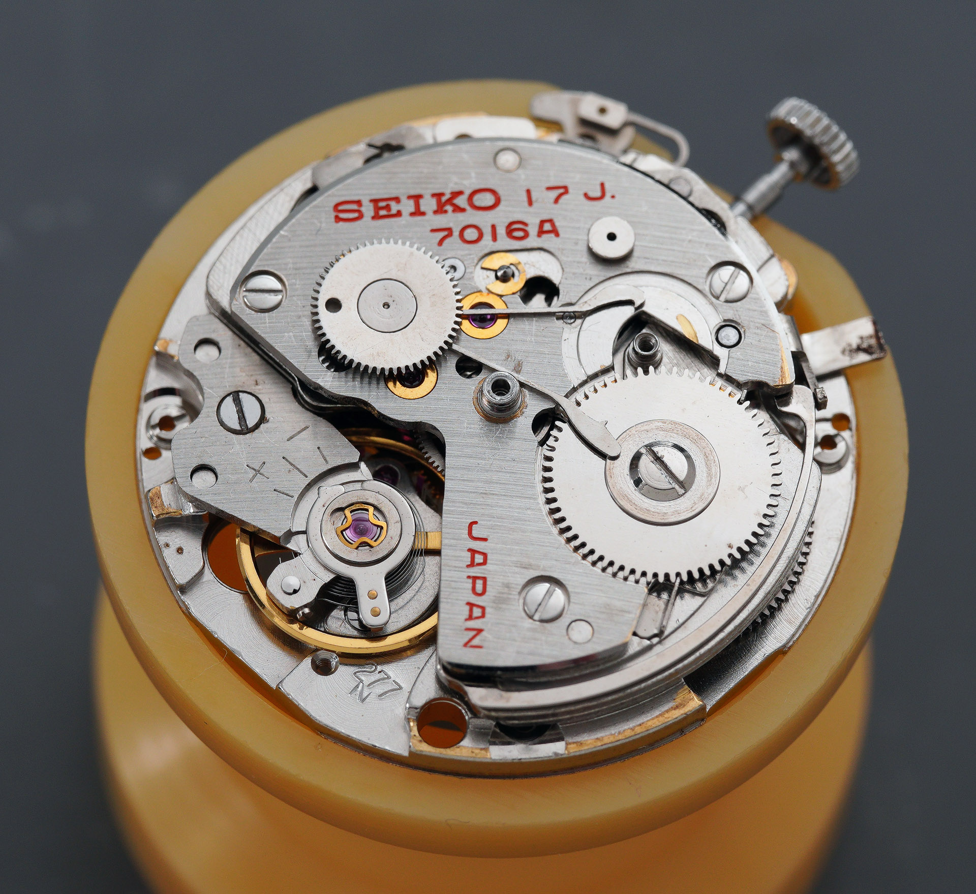
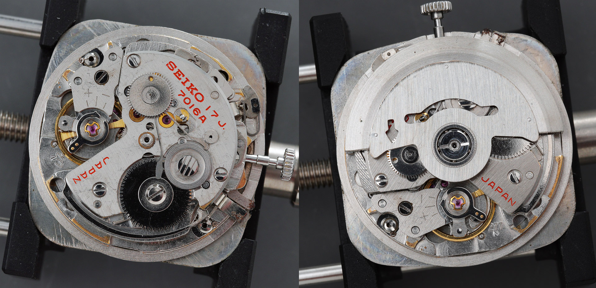
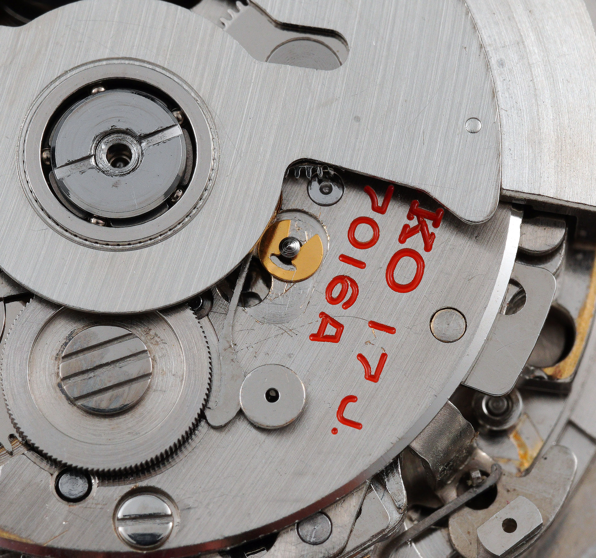
The presentation of the movement is typical of all 70-series, with the characteristically exposed workings of the magic lever autowinder mechanism. You can read about my thoughts on this family of movements in an earlier post on the related 7018 chronograph and how I acquired a new-found respect that overrode my previously held prejudice. More of that as we progress further. The winding weight is removed easily enough by unscrewing the captive screw that holds the central bearing to a threaded post at the centre of the barrel and train wheel bridge.
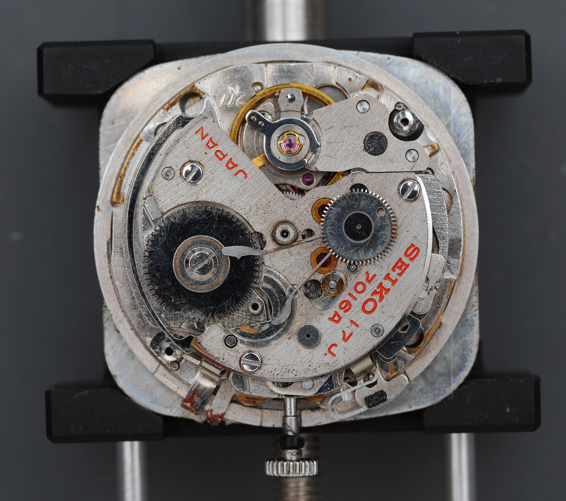
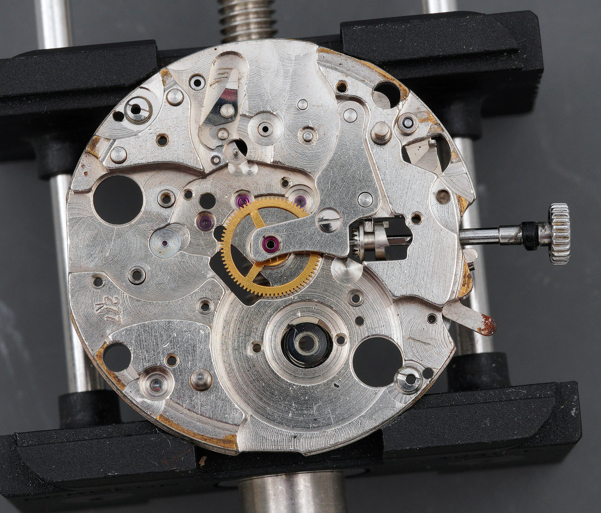
The appearance of the movement would appear to be inconsistent with it having been properly serviced in 2019. It is filthy and as we delve deeper, the initial impression that the most recent service was a ghost service is reinforced. Turning the movement over and placing it in a movement holder (this one not designed for the 7016 but rather the 7018), we can align the hour and minute hands in preparation for their removal.
You may be able to discern that there is a little paint missing from the edge of the yellow minute register hand, a sure sign of slippage during a previous removal. There is further evidence of damage to this and the hour register hand when viewing the two in situ from the side.
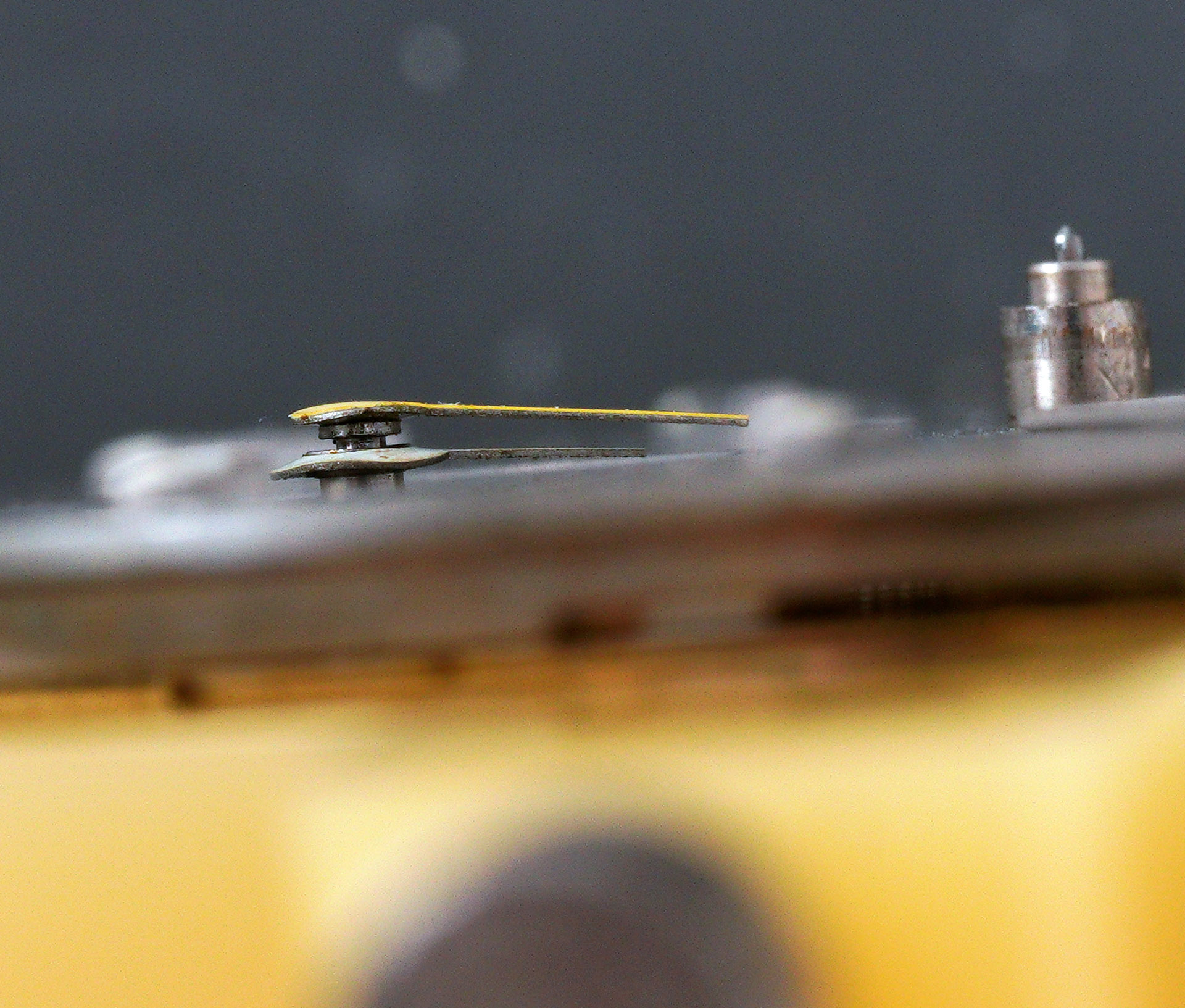
The floppy hat rims at the centres of both have been caused by a watchmaker using an oversized hand press during a previous refitting of the hands.
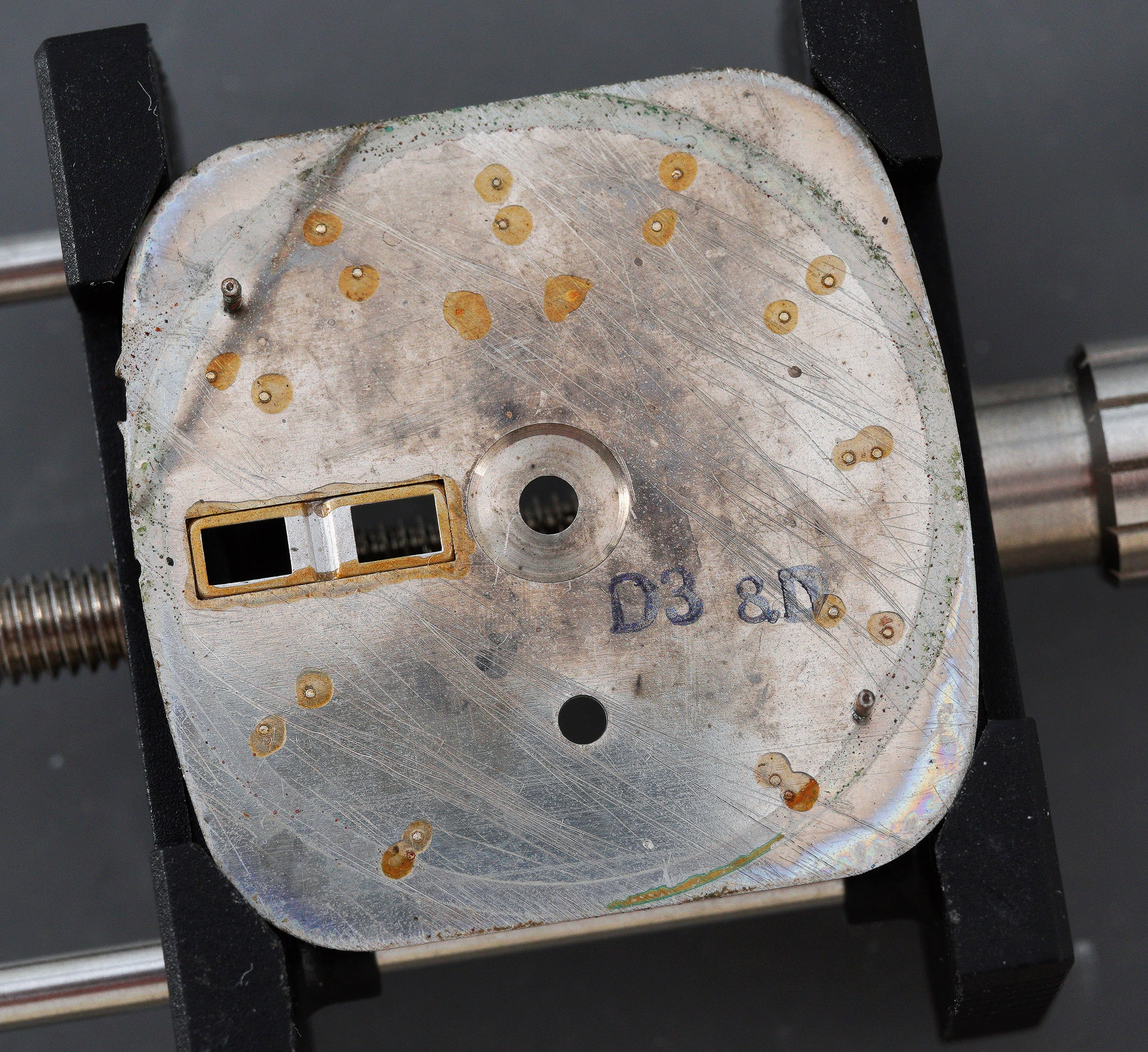
It is always interesting to take a look at the rear of the dial for manufacture date codes. In this case, the dial is marked by the code D3 8D. I don’t know the significance of the final two digits but the first two suggest that the dial may have been made in December 1973, more than a year later than the case. The later dial date would be consistent with this watch having been purchased new in 1974 and possibly provides a perspective on the relative timings of production of difference components prior to assembly of the completed watches. Usually, the dial and case date codes are much more closely aligned.
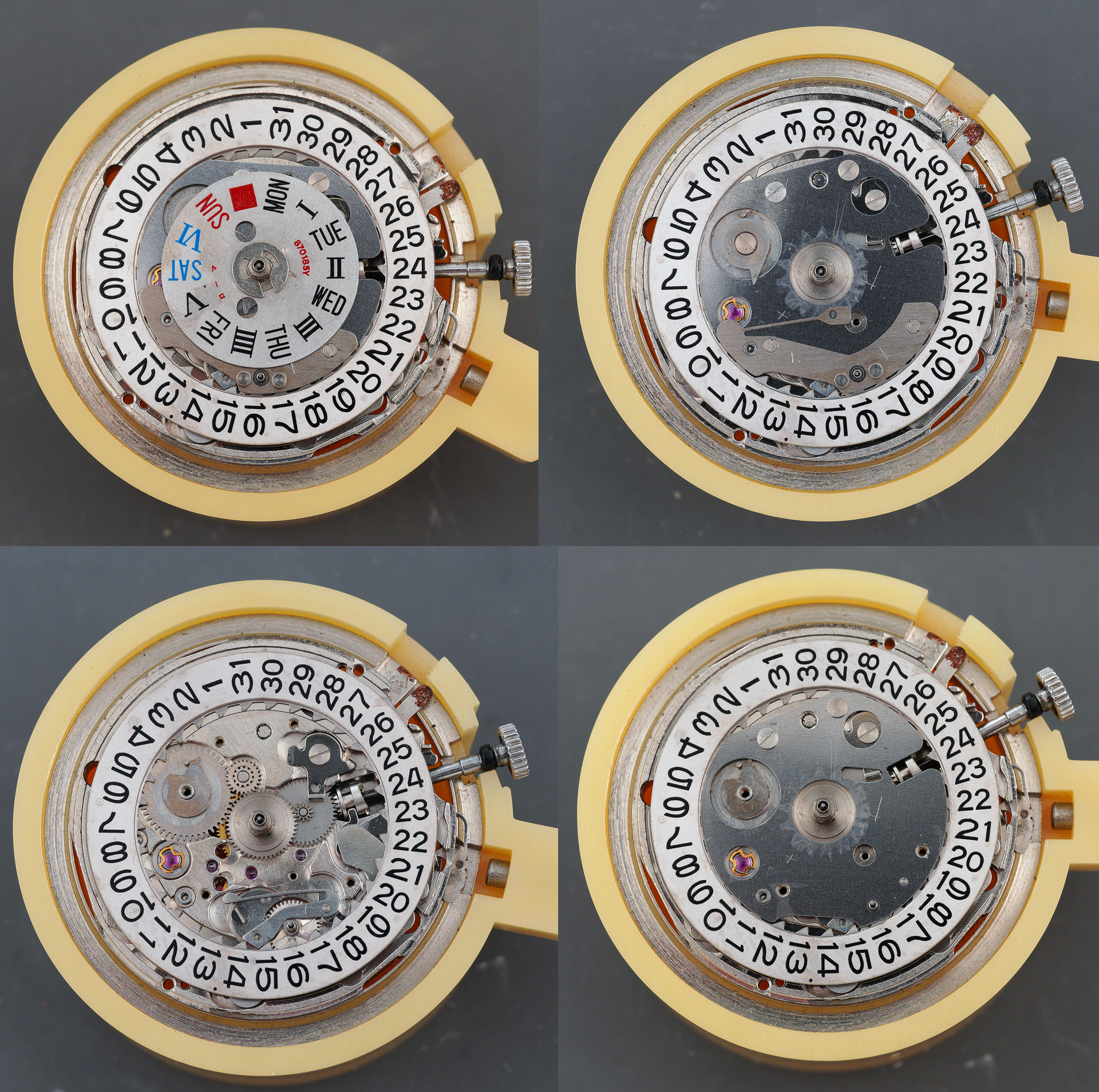
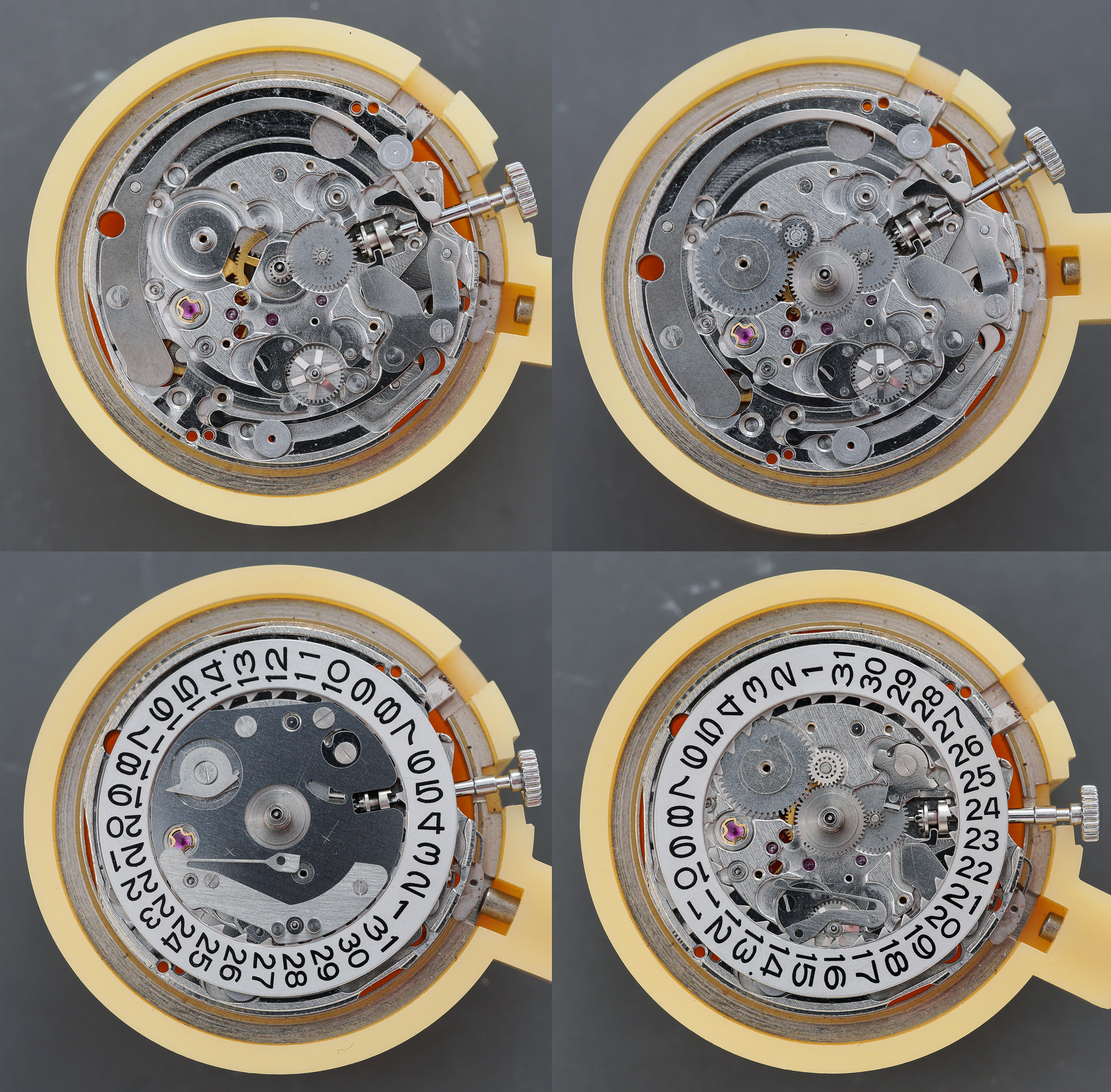
With the dial and hands removed, we can start to dismantle some of the calendar components on the dial side of the movement. The sequence shown below, clockwise from top left, charts the removal of the day disk, revealing the day jumper screwed to the date dial guard. The day finger has to be removed before the date dial guard at which point the layout of the setting and calendar components is revealed.
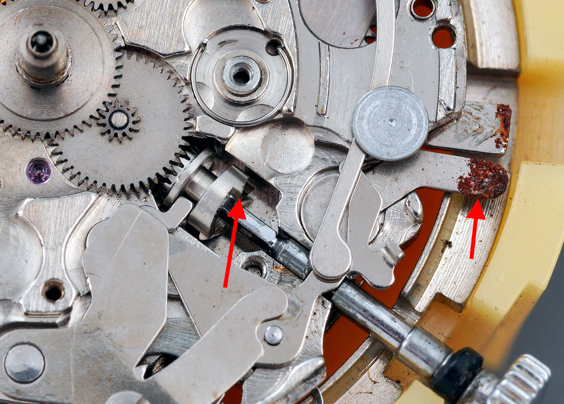
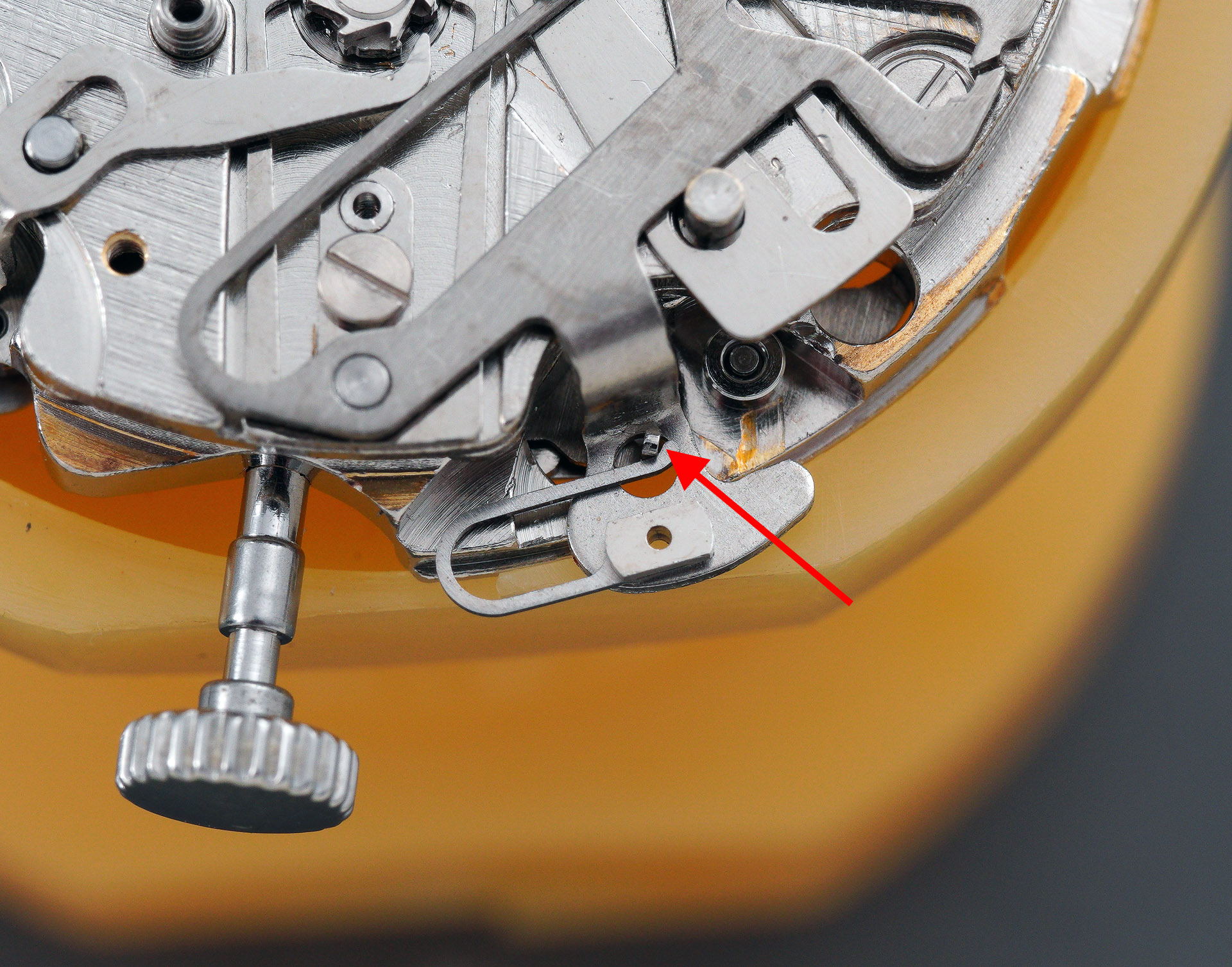
This movement features quickset day and date calendars with the date quickset operated by pulling the crown out to the first click and then rotating it anticlockwise; the day quickset operates by pushing the crown in from its zero position against the load of the day corrector spring (indicated below). The inwards motion of the crown pushes the setting lever against the day corrector (top right, below) which acts against one of the teeth of the star mounted on the rear of the day disk. The date quickset, incidentally, operates through the simple genius of a step on the rear of the clutch wheel hooking onto one of the inner teeth of the date dial. There are some really beautiful pieces of design on display here in a movement that also incorporates elements seemingly designed to infuriate.

The principal difference between this movement and the related 7018, described in a previous post, is that the 7016 incorporates an elapsed hour hand, concentric with the elapsed minute hand. The hour recording wheel that provides that function is indicated in white text in the photograph above. With the hour recording wheel removed, we can see the pinion of the intermediate hour recording wheel peeping through from the other side of the movement (indicated below). It is this that drives the hour recording wheel.
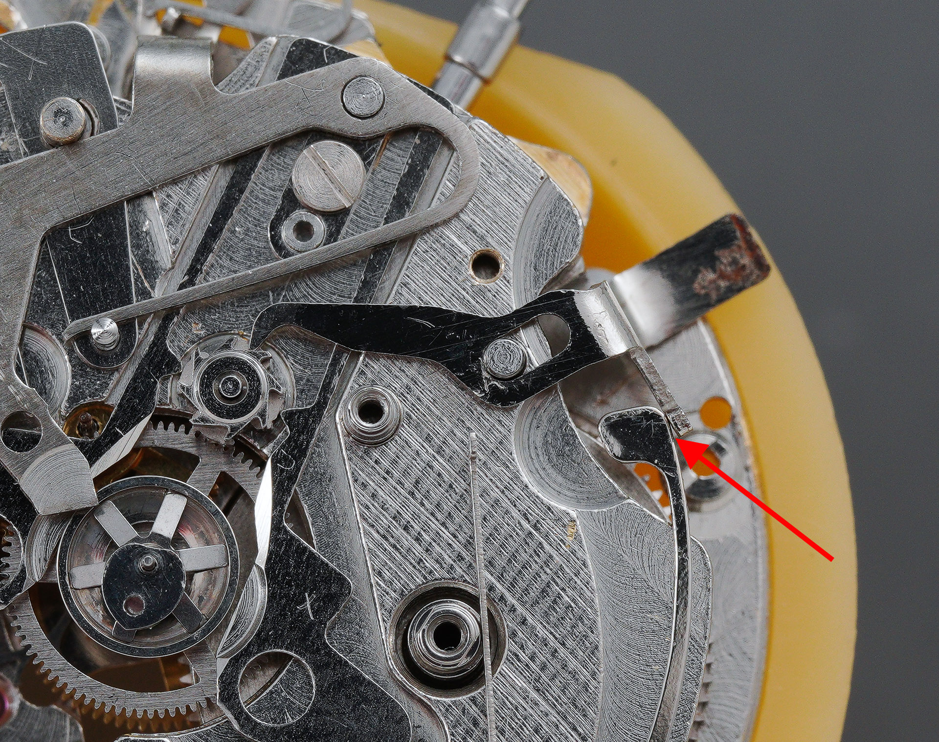
In the photo below, I’ve highlighted one of the teeth to the rear of the clutch wheel that facilitates the date quickset function. I have also indicated the rust evident on the tip of the stem unlocking lever used earlier during the removal of the stem. Clearly, some water has made its way into the interior at some point.
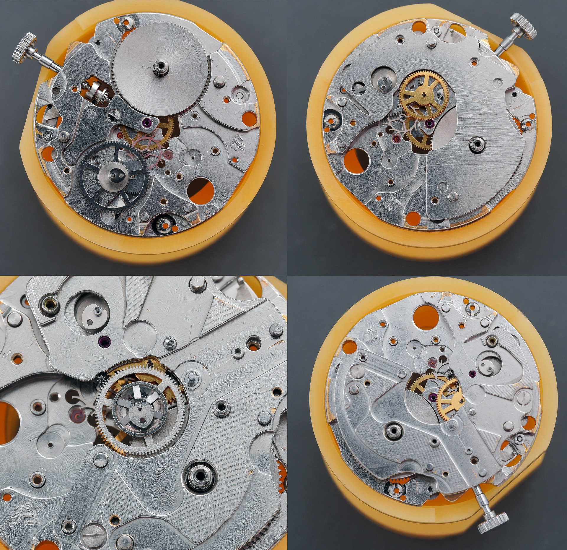
Turning the movement over, we start to tackle the train side by removing the Diashock setting from the balance wheel.

The balance can then be removed, exposing the escapement.
The integration of the magic lever autowinding mechanism into the barrel and train wheel bridge means that a particular sequence of operations is required before the train bridge can be removed. The first of these is to remove the ratchet wheel and second reduction wheel. It is worth noting again just how dirty the bridge is and how worn the plating is in the vicinity of the second reduction wheel vacancy.
The final task before we can remove the three screws and then the bridge, is to remove the copper-coloured retaining clip, referred to as the barrel and train wheel bridge holder in the technical manual (see photo above). This clip fits onto a post protruding from the chronograph bridge, one level down. With that done, we can remove the train wheel bridge.
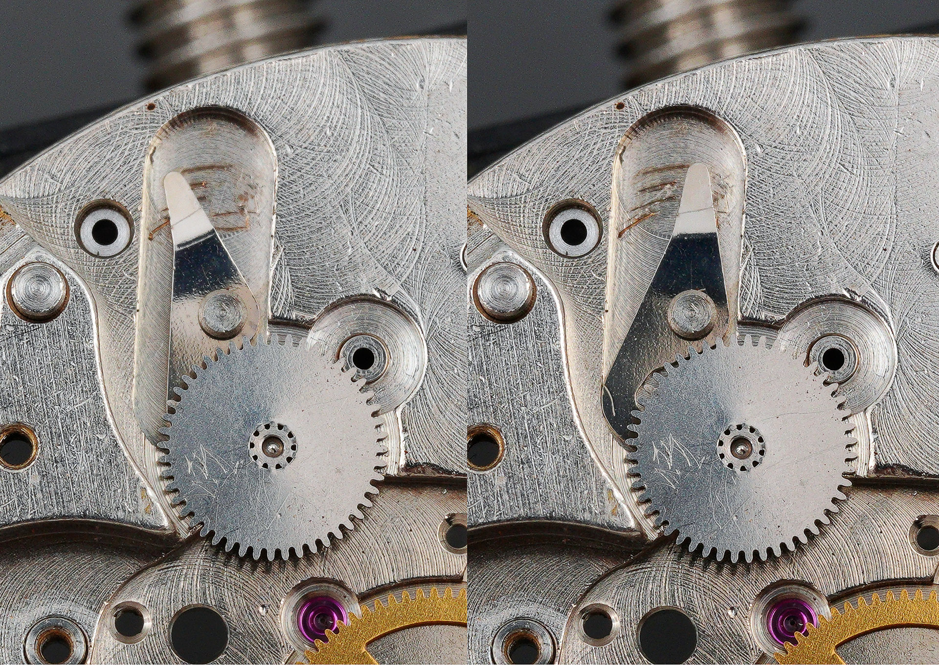
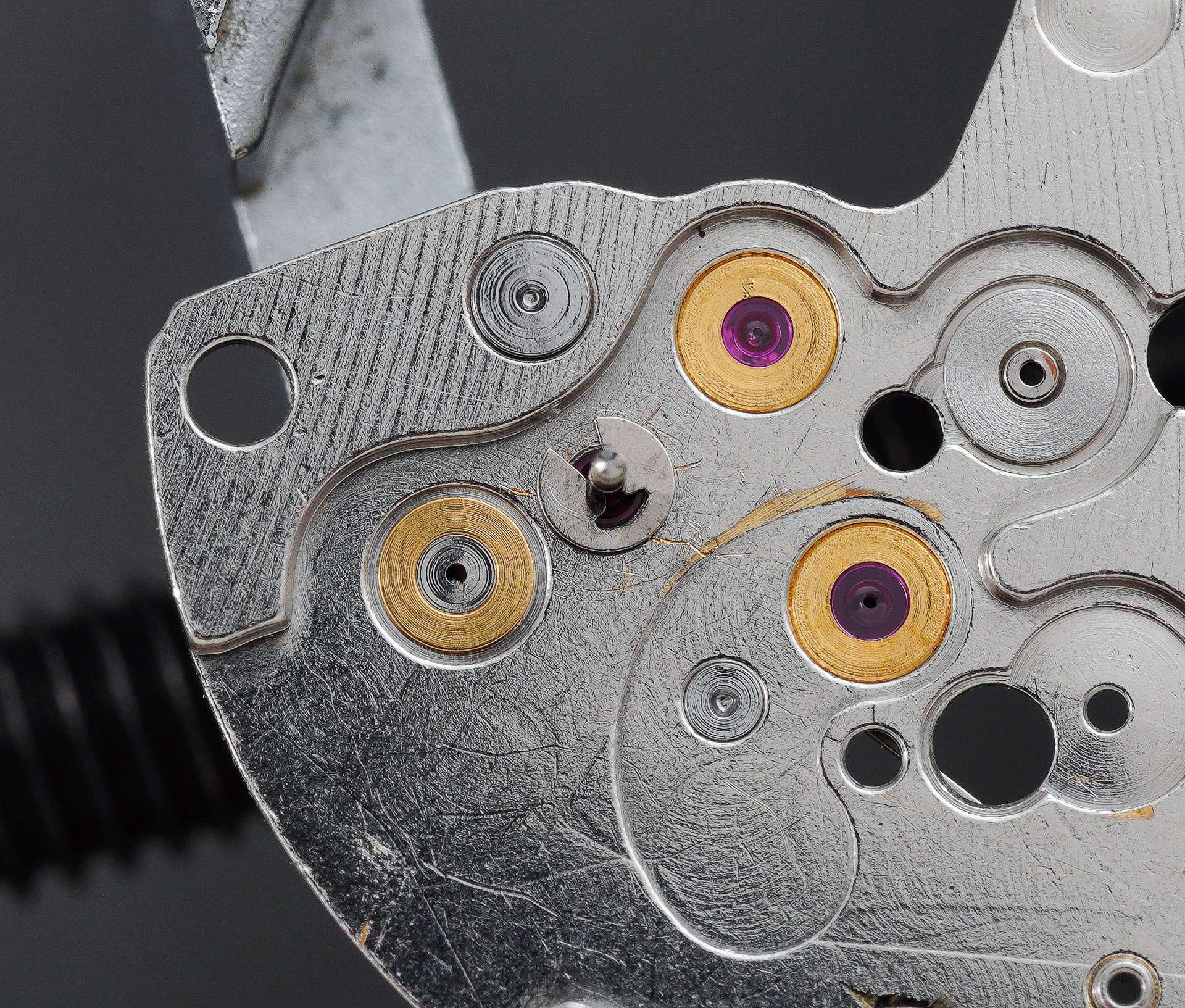
The first reduction wheel and pawl lever are secured to the bridge by a retaining clip on the underside of the bridge, indicated in the photo above. Removing that clip frees the first reduction wheel and we can survey the condition of the jewelled bearing in which its shaft rotates.
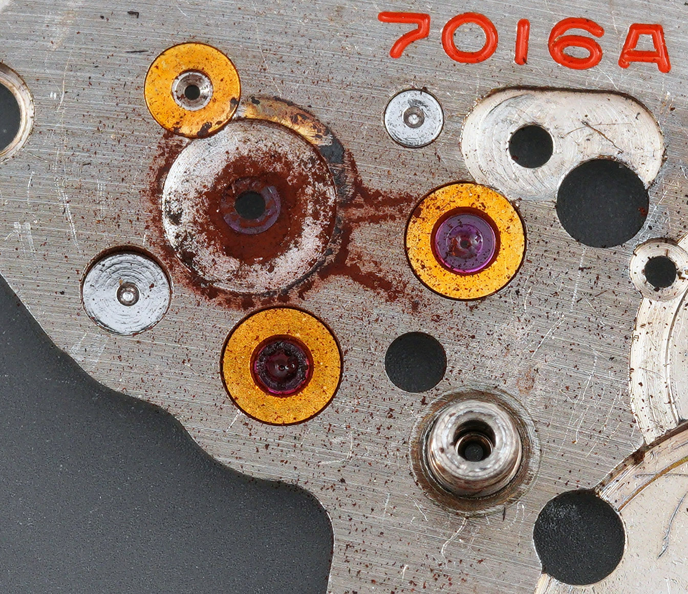
Oh dear. I think we may have identified why the automatic winding mechanism wasn’t working. If you look closely at the jewel, you may be able to see that it has disintegrated. We’ll take a closer look a little later once I’ve cleaned away all of the crud.
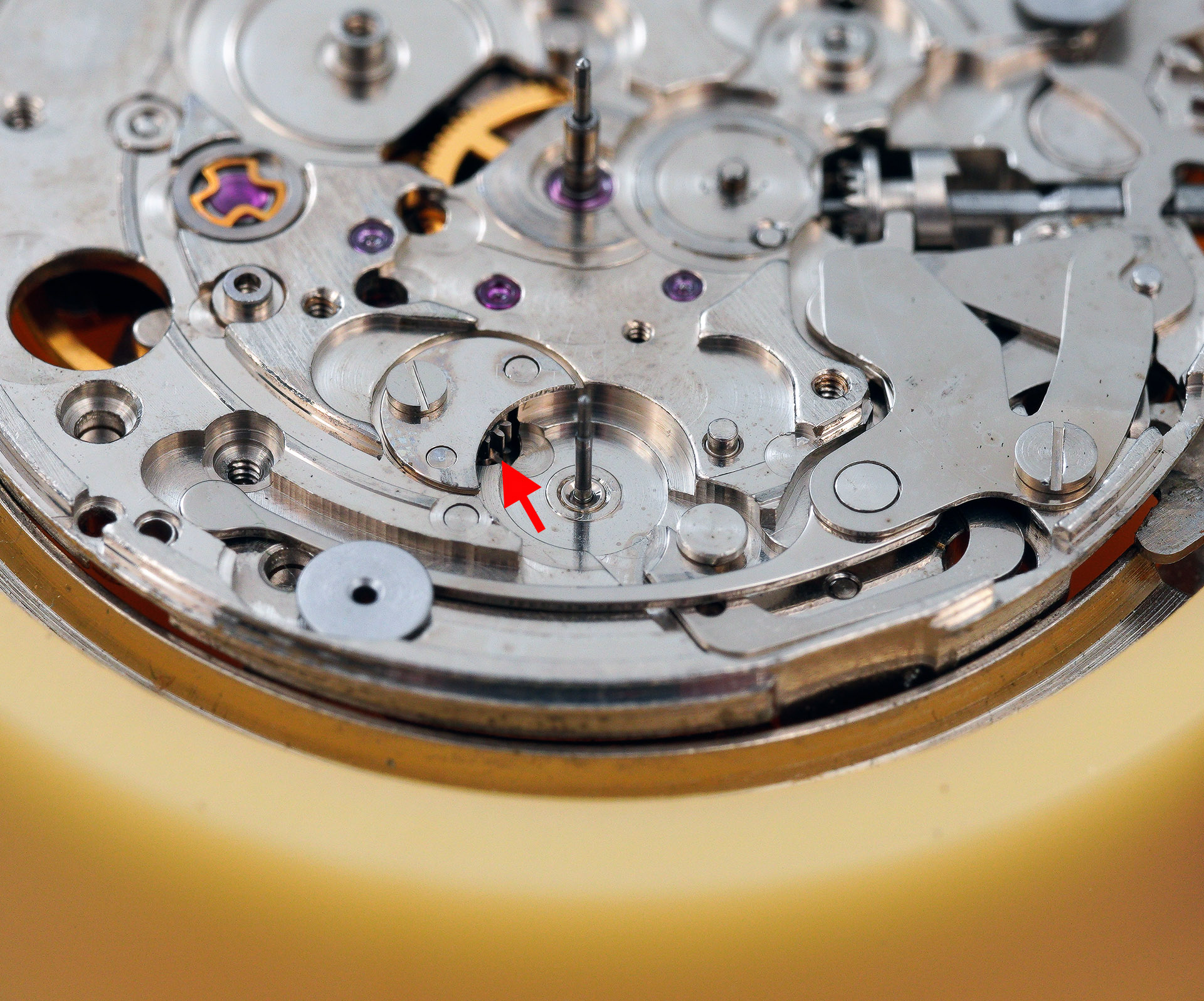
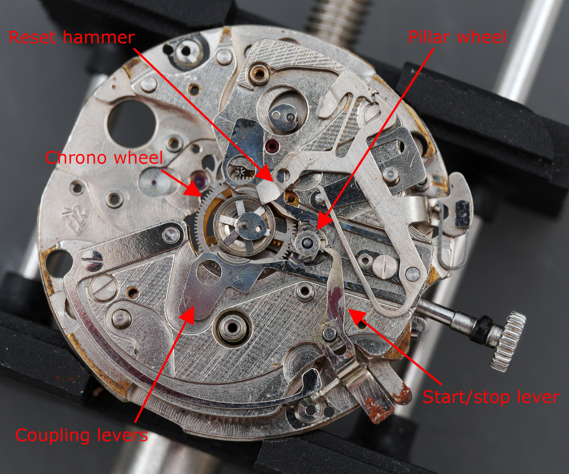
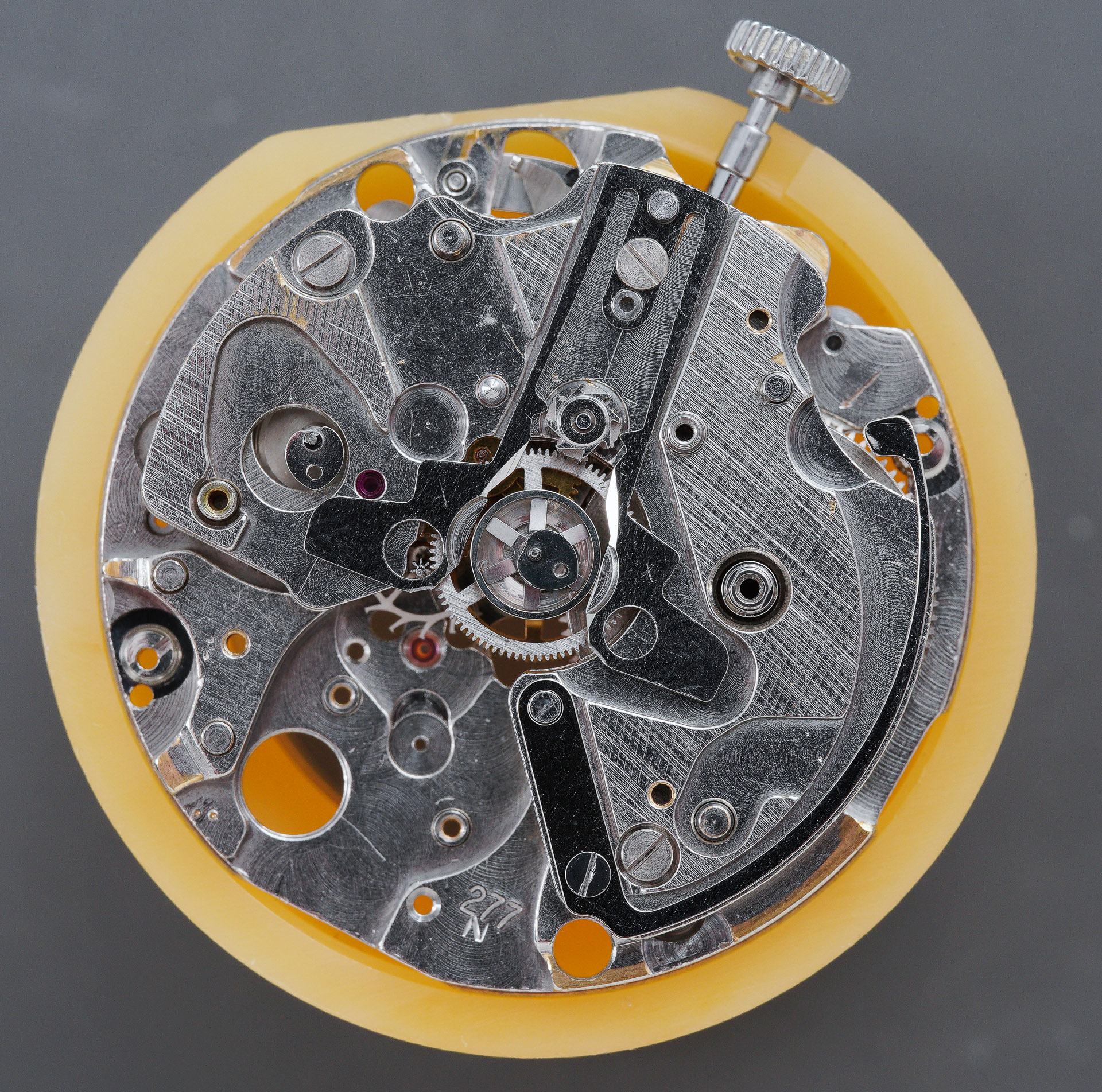
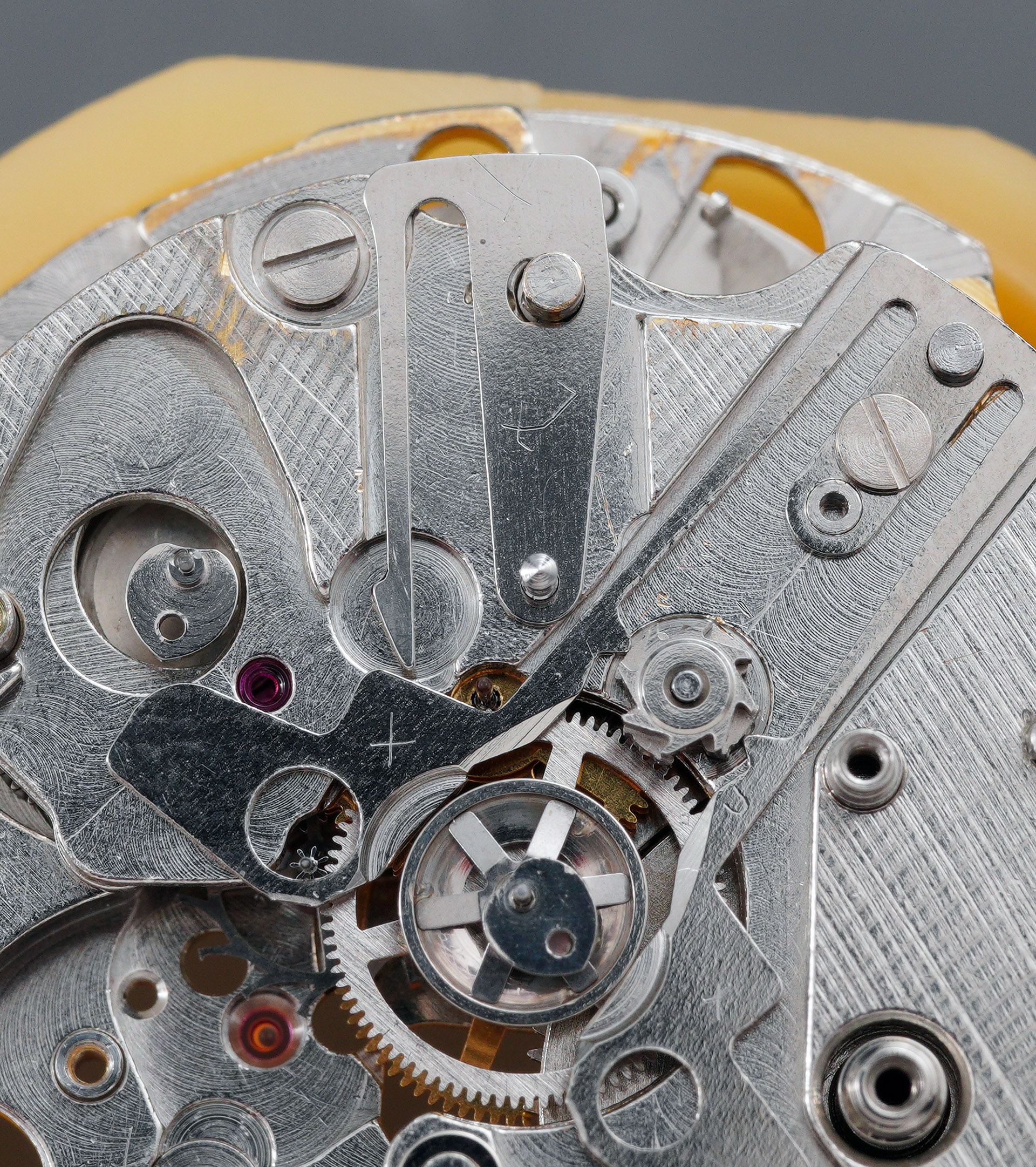
With the train bridge out of the way, the complexities of the chronograph mechanism are exposed. I’ve indicated some of the key elements in red and you can read more detail about how this all works in the earlier post on the 7018. In brief though, the chronograph wheel employs a vertical clutch that is released or engaged by the action of a connected pair of coupling levers that compress or decompress depending on the position of a captured pillar wheel (you still with me?). The scissoring inwards of the coupling levers separates the top part of chronograph wheel from the fourth wheel, decoupling the central seconds hand. In this condition, the chronograph is stopped. Releasing the coupling levers allows the two parts of the clutch to re-engage and the central pinion can rotate once more in concert with the fourth wheel.
The next step is to remove the hammer but first we need to release the hammer spring from the pin beneath.
We are now free to remove the hammer, hammer click, coupling levers and operating lever.
The chronograph wheel is unrestrained at this point and lifts straight out. As in the 61-series chronographs, a potential vulnerability is that the clutch spring becomes weakened if left in its compressed state for extended periods of time. If that happens, it will start to slip.

The result is that the chronograph appears to run fast as the momentum of the forwards moving seconds hand carries it further than intended with each ‘tick’ and it gains time. An initial examination of this original part suggests it is healthy but the proof of the pudding will be in the eating when we get to see it in action (hopefully). Note also in the photograph that the tip of the shaft it profiled. The first fit of the seconds hand mates it for life with this shaft. In the event of a divorce, the shaft may couple with a fresh hand but the used hand may not form another union with a different shaft. Hopefully that makes some sort of sense.
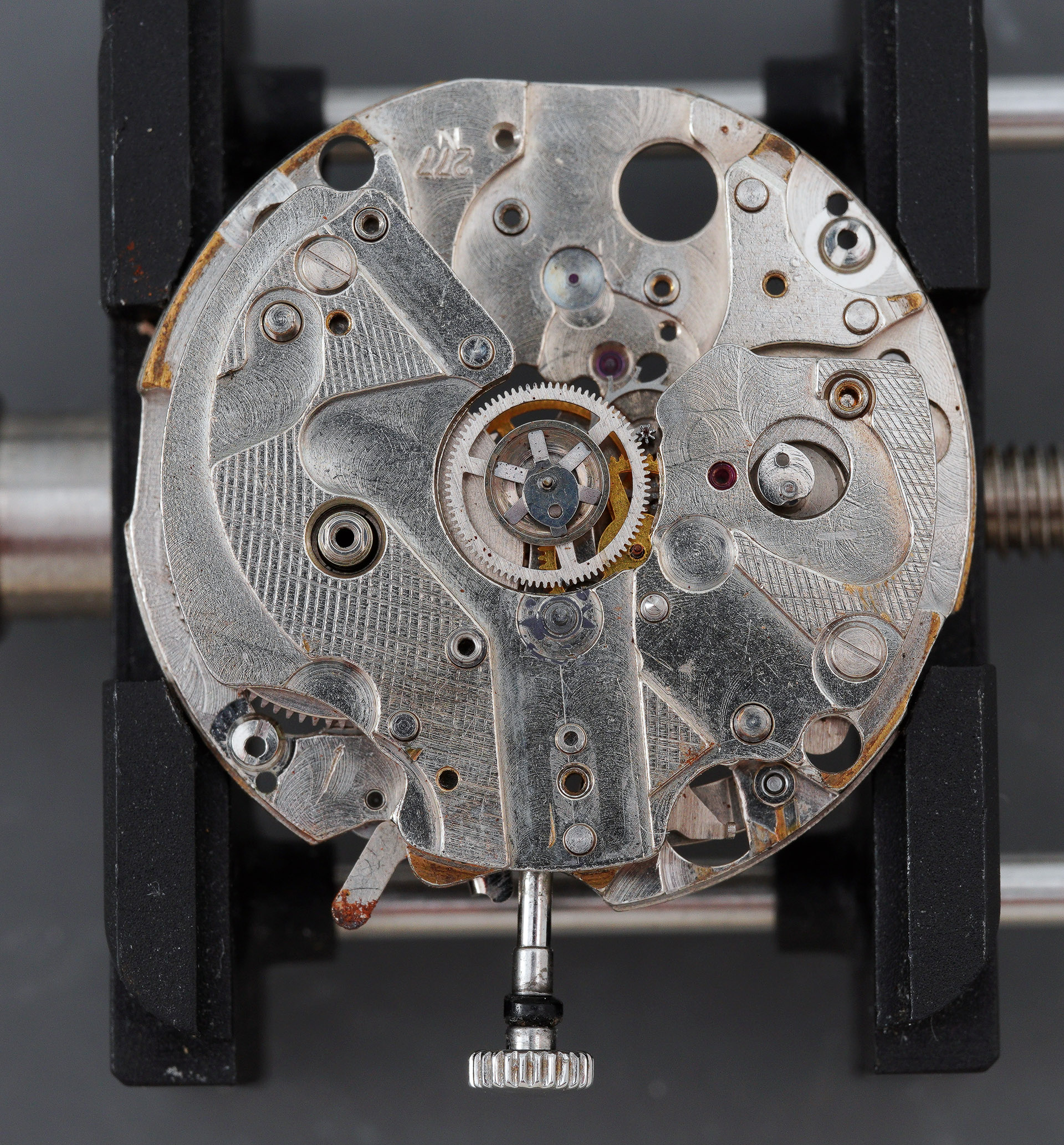
The chronograph bridge is held in place by two screws and with those removed, we can peel away another layer of this particular onion to reveal the lower plate for the chronograph bridge (below, left).
That is unsecured and its removal, taking care not to snag the heart of the minute recording wheel, provides, finally, a view of the going train of the movement: barrel, centre wheel, escape wheel and the double-stacked third wheel. The upper-most wheel is the minute recorder wheel on whose shaft will be mounted the small elapsed minute hand in due course.
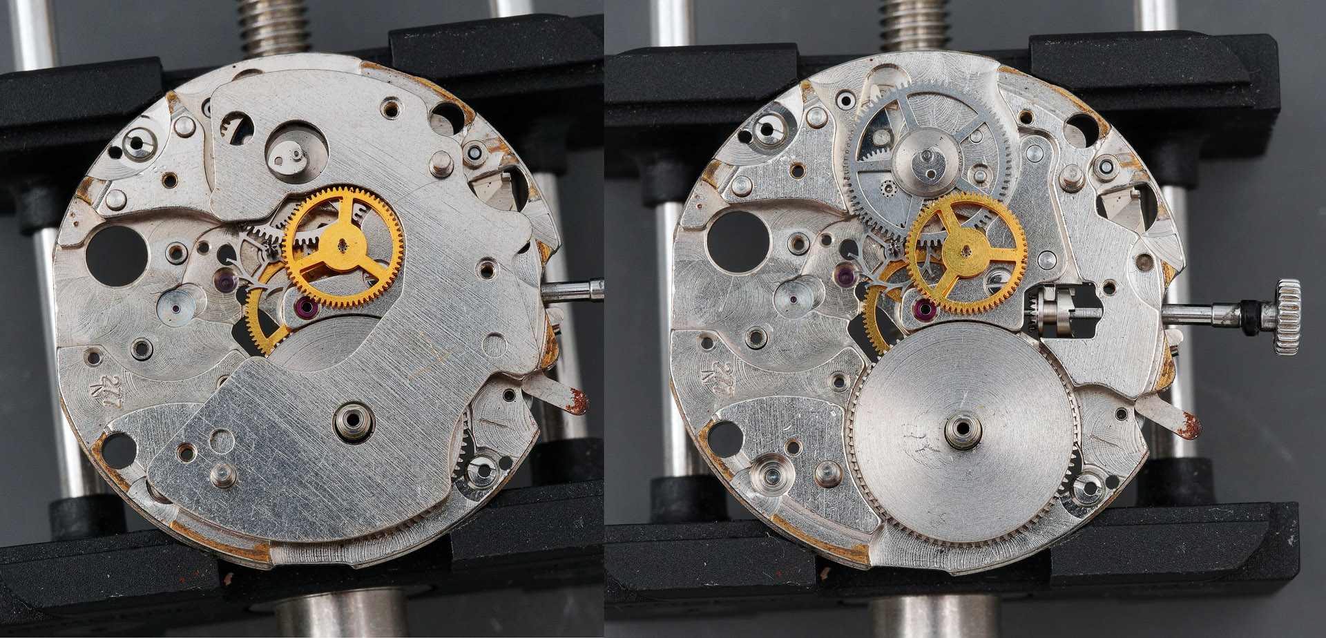
The third wheel, minute recording wheel and escape wheel are removed next but in order to remove the intermediate hour recording wheel, we have first to decouple its moveable bridge by rotating it clockwise until the wheel is released (left to right, below).
That then leaves just the centre wheel and its bridge left in position on this side of the movement.
The completion of the denuding of the main plate is achieved by removing the cannon pinion on the other side, then the centre wheel bridge and centre wheel from the train side and we are just left with a few final setting parts left to remove before cleaning.
The next task is to lift the lid on the barrel and inspect the mainspring.
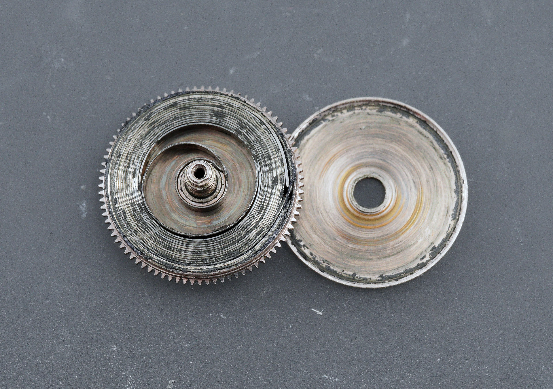
Everything looks fine and that initial impression is reinforced once the mainspring is released from its enclosure.

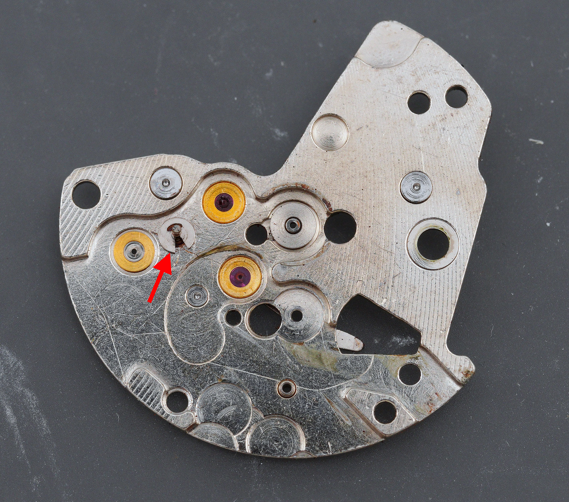
Before submitting all of the parts to the cleaning stage, I wanted to tackle the mangled autowinder jewel. Having undertaken a preliminary clean of the bridge to remove all of the detritus, a closer inspection of the jewel reveals the extent of the damage.
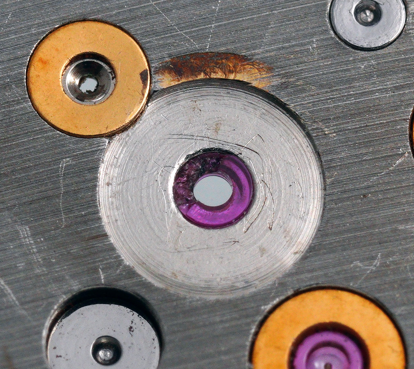
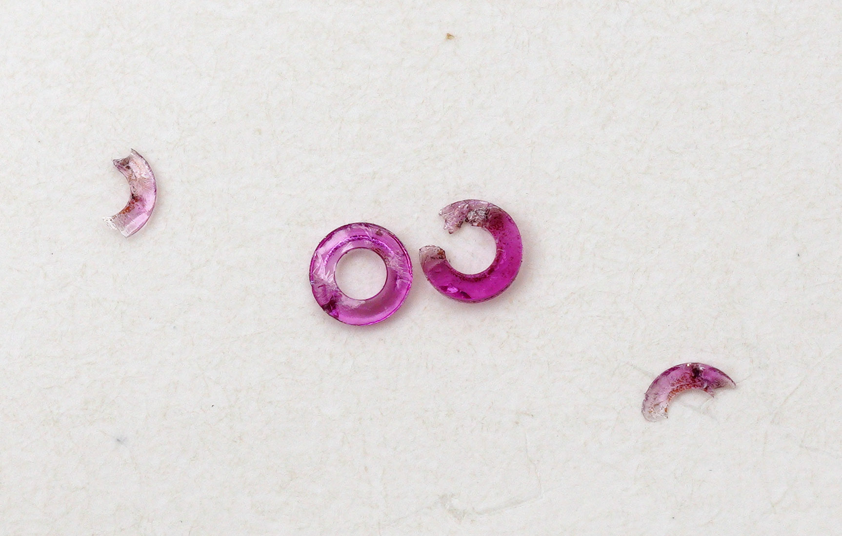
It is often the case that the full extent of the fragmentation of a jewel in this sort of state is not completely revealed until it is pressed out of its setting.
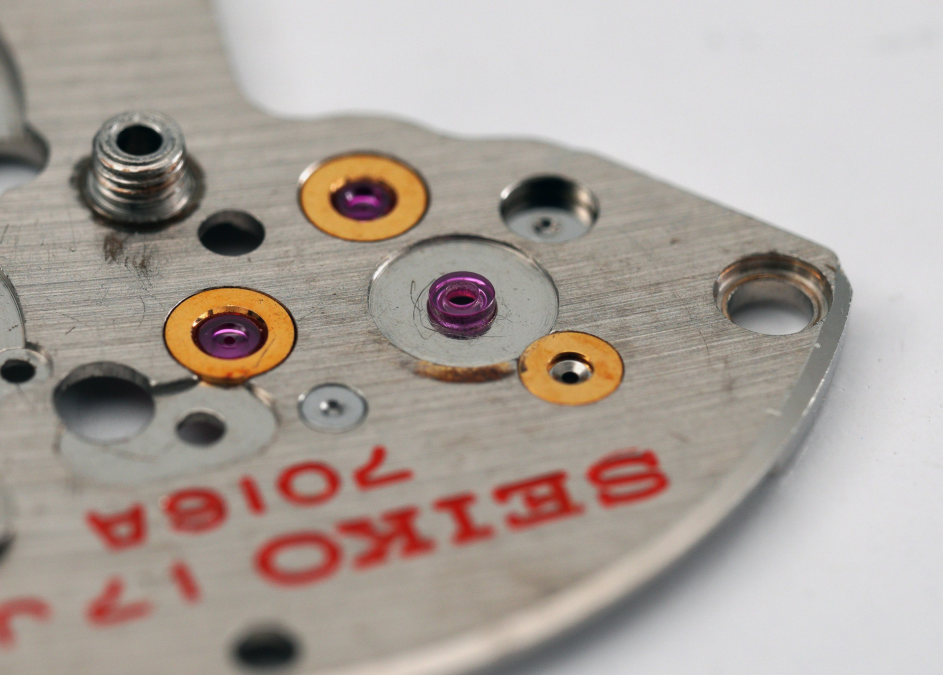
The part number for this jewel is 011162 and is available from Cousins and so I secure a replacement along with a new first reduction wheel, a replacement barrel and train wheel bridge holder and the clip for the first reduction wheel.
A day or two later, the replacement jewel is placed into position ready to be pressed into its hole.
The process is completed with the aid of a Horia-style jewelling tool.

I will make some final adjustments to its position during the reassembly process but for the moment we are now ready for all of the parts to find their way to the cleaning machine.
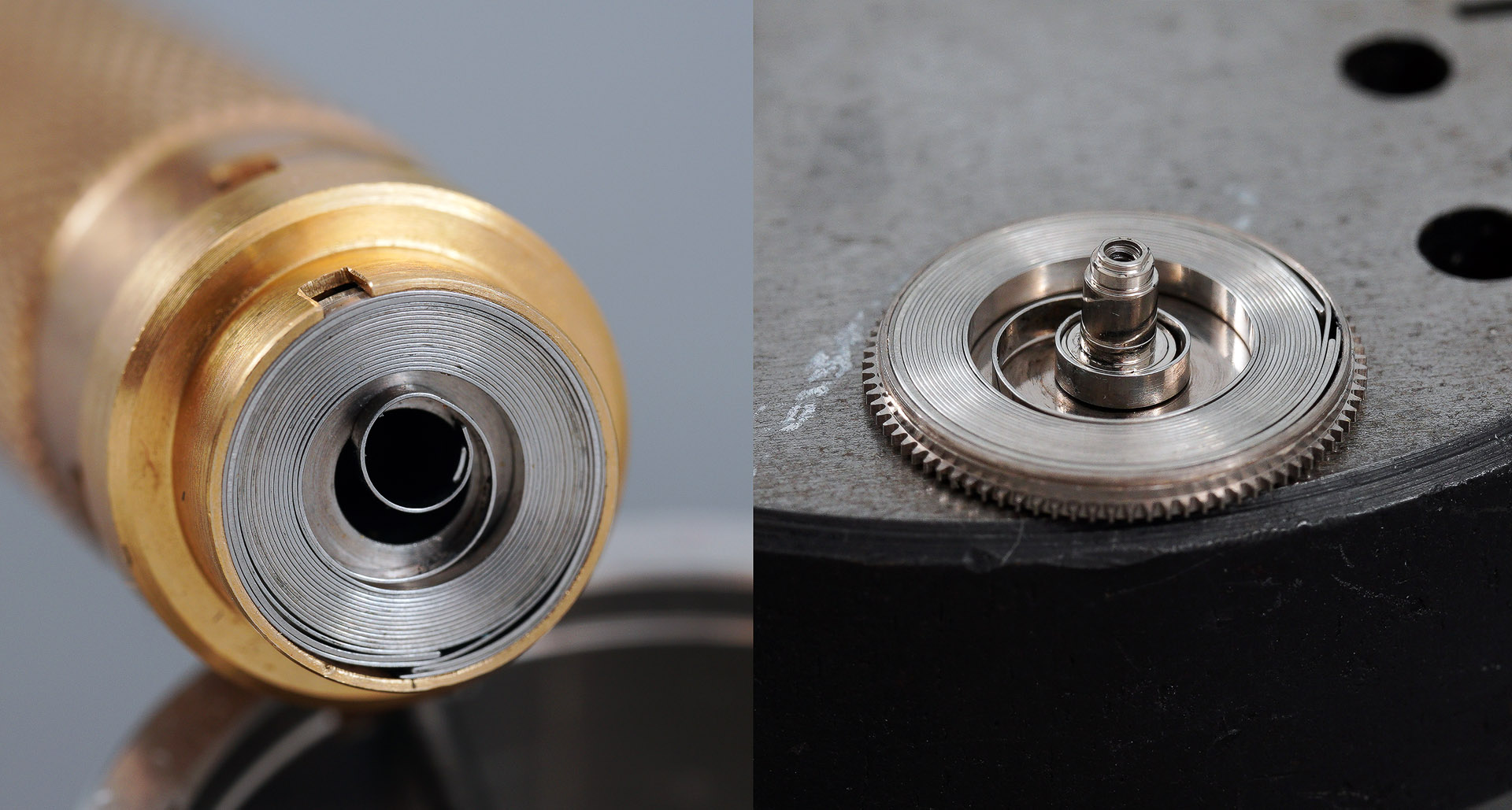
The first job once all of the parts have been cleaned and dried, is to fit the cleaned mainspring back into the barrel. The mainspring is wound clockwise in the barrel when viewed in situ which means it needs to be wound anticlockwise into the winding drum in preparation for its reinsertion and that ideally requires a left-handed winding arbor. Rather than persist in adopting my improvised solutions to this issue in perpetuity, I have recently purchased a couple of the most common sizes of left-handed Bergeon arbors and I put one of these to good use here.
I have used Seiko S3 braking grease on the walls of the barrel and a very light application of 8200 on the mainspring itself. With that done, we can begin to build up the main plate, starting with the setting parts. The order of play is essentially the reverse of the deconstruction process: having set the clutch, stem, yoke, setting lever and its spring (top left and right, below), we turn over the main plate to fit the centre wheel and its bridge (bottom right, below) and then back to the dial side to fit the crescent-shaped plate that will cover the intermediate hour recording wheel (bottom left, below).
Psst. Don’t tell anyone, but I’ve neglected to install the lever to unlock the stem because its installation is not part of the numbered sequence in the technical manual. Not a disaster because I can and will rectify this omission further down the line. For the moment, the unseen vacancy quietly mocks me.
At this point, we can start to assemble the gear train, starting with the mainspring barrel, escape wheel, intermediate hour recording wheel (not forgetting to swing the levered bridge back into position, the minute recording wheel and the third wheel (top left, below). The lower plate for the chronograph bridge comes next but we must first make sure to direct the tip of the minute recording wheel heart towards the balance hole to allow it to clear the hole in the plate (top right, below). The chronograph bridge follows (bottom right, below) at which point we can lower the chronograph wheel into position (bottom left, below).
Where the coupling levers in the 6138/9 are a separately-mounted pair, in the 70-series chronographs, the coupling levers form a single part referred to curiously as the balance stop lever in the Seiko technical manual. Don’t ask me why it’s called that because its function is emphatically not to stop the balance but rather to stop the chronograph.
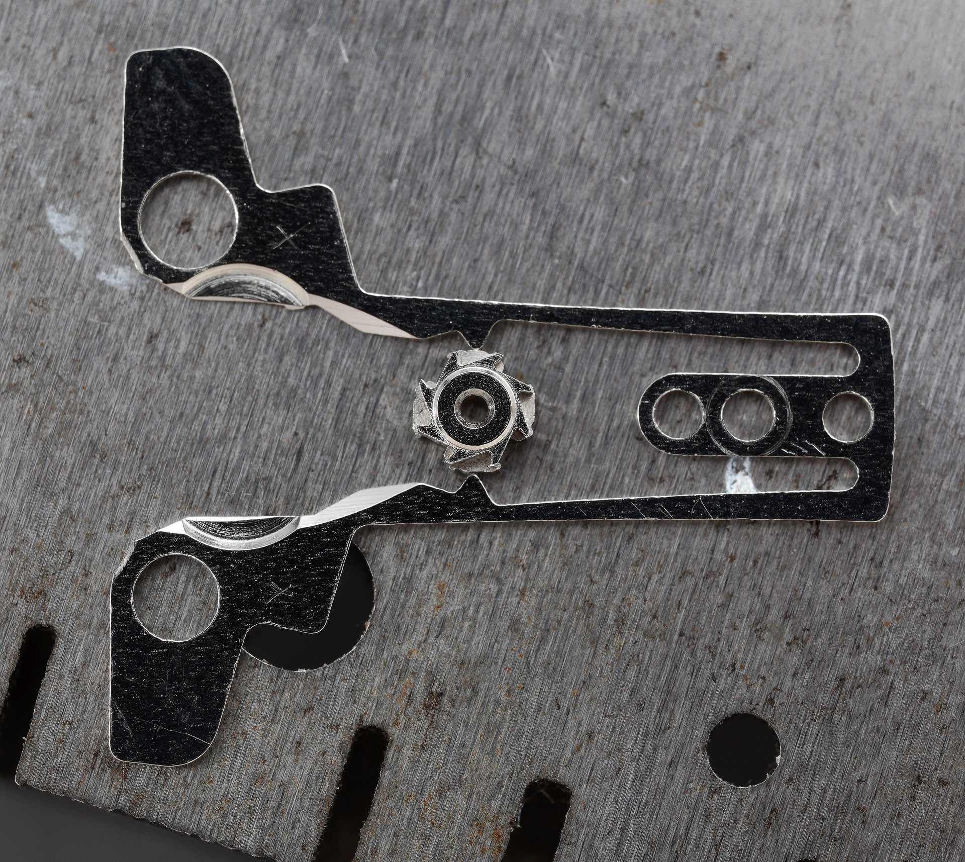
Before fitting this part, you have first to insert the pillar wheel (as shown above), oriented to ensure that the two levers are in their most-separated position (so as to clear the chronograph wheel clutch ring when being fitted). The next step is to do just that, followed by the operating lever spring.
The hammer click comes next at which point we must brace ourselves for the supremely fiddly challenge of fitting the hammer.
A successful execution of this task requires three hands and all fifteen fingers and the ability to conjure up all manner of colourful expletives. Somehow, I seem to have accomplished this task.
The last step requires the swan neck spring to be positioned behind the hammer pin.
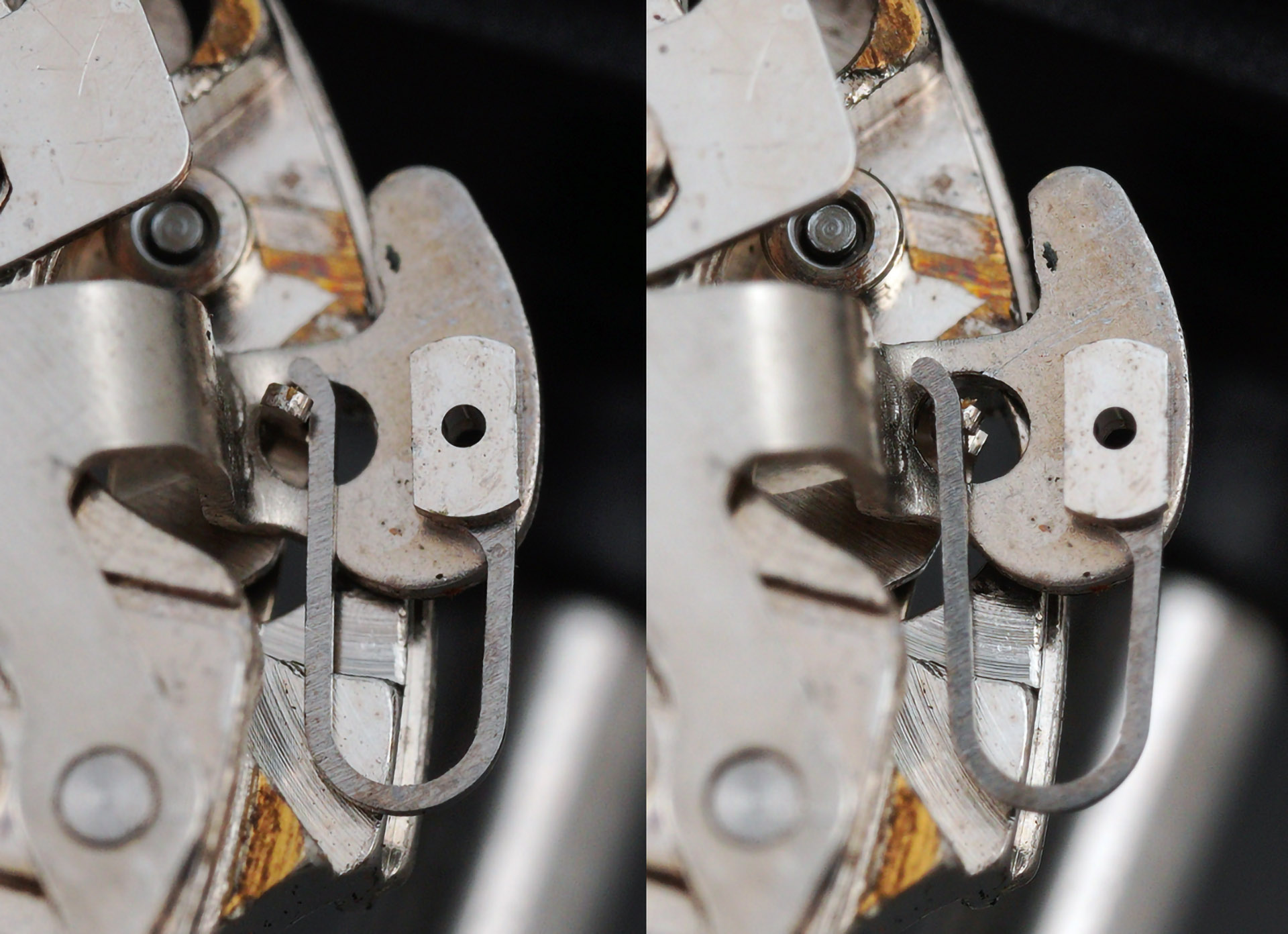
The final component of the chronograph mechanism is the operating lever – the lever that connects the start/stop button with the pillar wheel mounted at the centre of the balance stop lever. In fitting this part, we must ensure that the end of the operating lever spring sits inside the arm protruding from the side of the lever (indicated in red, below).
Before we can tie this lot down with the barrel and train wheel bridge, we have to fit the autowinding mechanism to the bridge: specifically, the first reduction wheel and pawl lever.
At this point in proceedings, I am reusing the original first reduction wheel but will in due course replace that with the new item ordered earlier. The first reduction wheel is secured into place using the circlip mounted to the underside of the bridge.
We are all set to refit the barrel and train wheel bridge, ratchet wheel and then the escapement.
As it turned out, there were two elements that made this a tricky undertaking: the first was the issue of getting all of the wheel shafts to line up with the holes in the bridge but we also have to make sure that the operating lever and hammer are not inhibited as the bridge is tightened down. I found it helpful to perform a couple of start/stop actuations of the operating lever as I was battening down the hatches and that ensured that the gear train was running freely before fitting the escapement.
The only thing now that sits between this as a static object and as a running movement is the fitting of the two balance Diashock (antishock) settings and the balance itself. We start with the dial-side Diashock.
The balance is manoeuvred into position next, topped off with its Diashock, and with some power wound into the mainspring, she’s off and running.
With the reassurance provided by a ticking movement, we can press on and address once more the dial side of the movement and the reassembly of the calendar parts. In the sequence below, beginning top left and moving clockwise, I have refitted: the day corrector spring, cannon pinion, minute wheel and hour recording wheel; the date driving wheel, date finger, the intermediate date wheel, the hour wheel; the date corrector and its spring (in the reverse order), the date jumper and the date dial; and lastly, the date dial guard, day finger, date driving wheel screw and the day jumper.
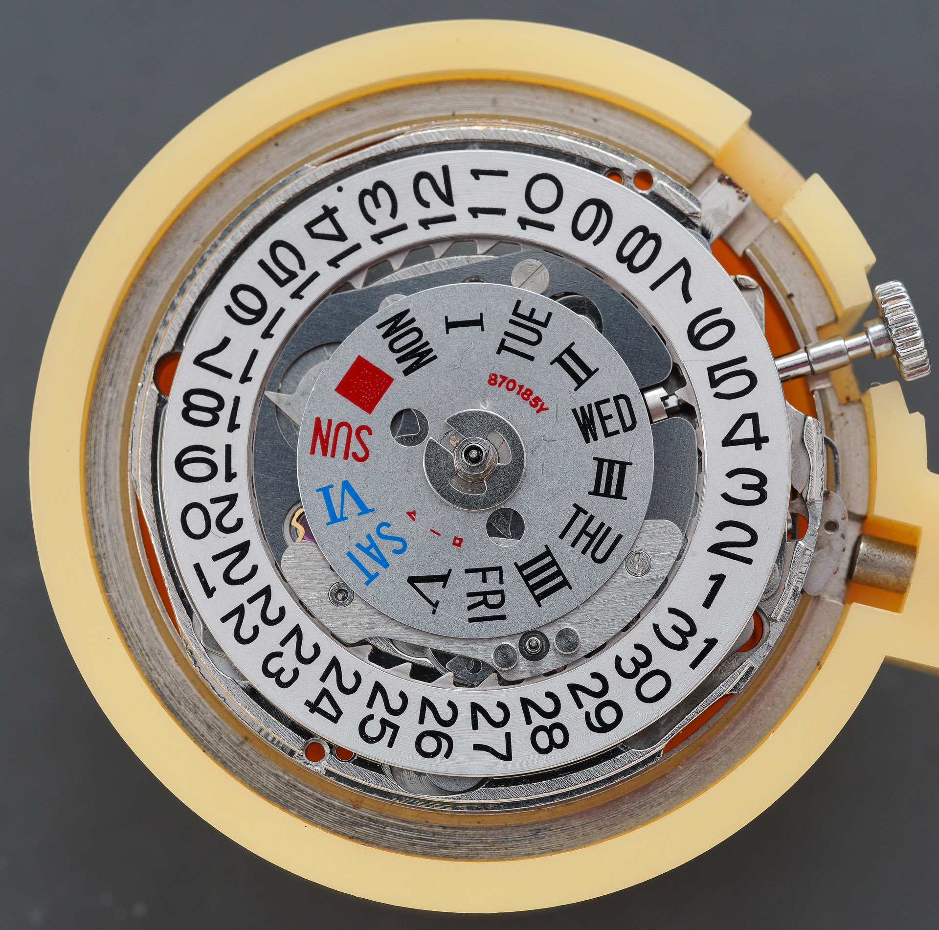
The day disk was pretty grubby and needed a clean with some Rodico before being presentable enough to be refitted.
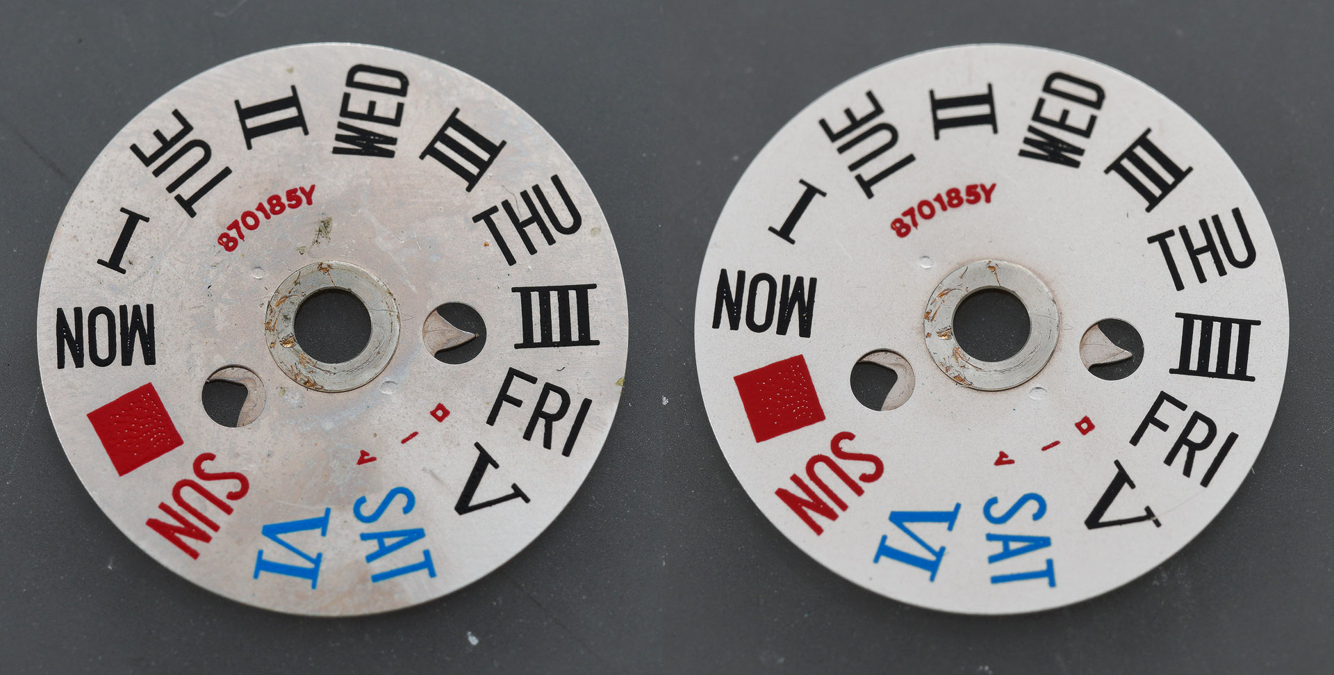
This is a dual-language day wheel and the use of Roman numerals for the second language suggests a general-purpose international configuration, in keeping with the suggestion towards the beginning of this article that the 7016 chronographs were largely destined for overseas markets.
With the day wheel in position we are ready to fit the dial and then start the process of fitting all five hands. We begin the latter by fitting the two sub-dial hands, having ironed out a little of the warping inflicted by a previous watchmaker, and then the hour hand.
The hour and minute recorder hands need to be fitted while depressing the reset lever to ensure that they properly align with the 12 marker when the chronograph is reset. Not having the correct 7016 movement holder makes this more challenging than it otherwise might have been but I managed to perform the task using the S-510 movement holder designed for the 7018. Before moving on to the minute and seconds hands, I make sure that there is sufficient clearance between the hour hand and the minute recorder hand.
The hour hand is fitted so that it aligns with the 12 marker as close as possible to the point that the date wheel ticks over at midnight. I usually perform a preliminary alignment of the minute hand with the hands set to 6 o’clock and then a tweak at 9 o’clock, if required. The final job is to fit the elapsed seconds hand, again while holding down the reset button. It is worth noting, as mentioned earlier, that the profiling of the seconds hand shaft means that the precise alignment is defined as that achieved by whomever first fitted this particular hand.

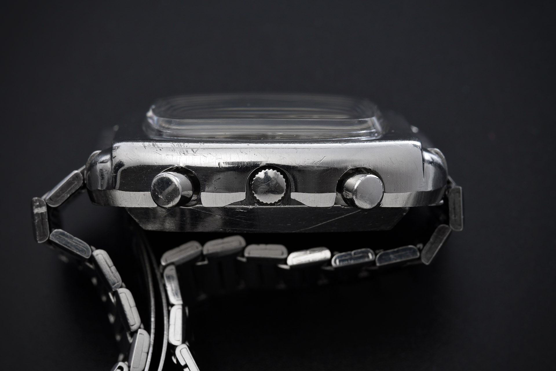
A second regulation at this point sees amplitude between 250 and 270 degrees, a nice clean timing curve and a beat error of less than 0.2 ms. This marks the conclusion, almost, of the movement work and so we are free now to move on to the case. The case is badly in need of a clean but before we get to that, we need to remove the chronograph pushers. Each pusher is secured to the case using a circlip and so each of these needs to be removed first before being able to withdraw the pushers from the case.
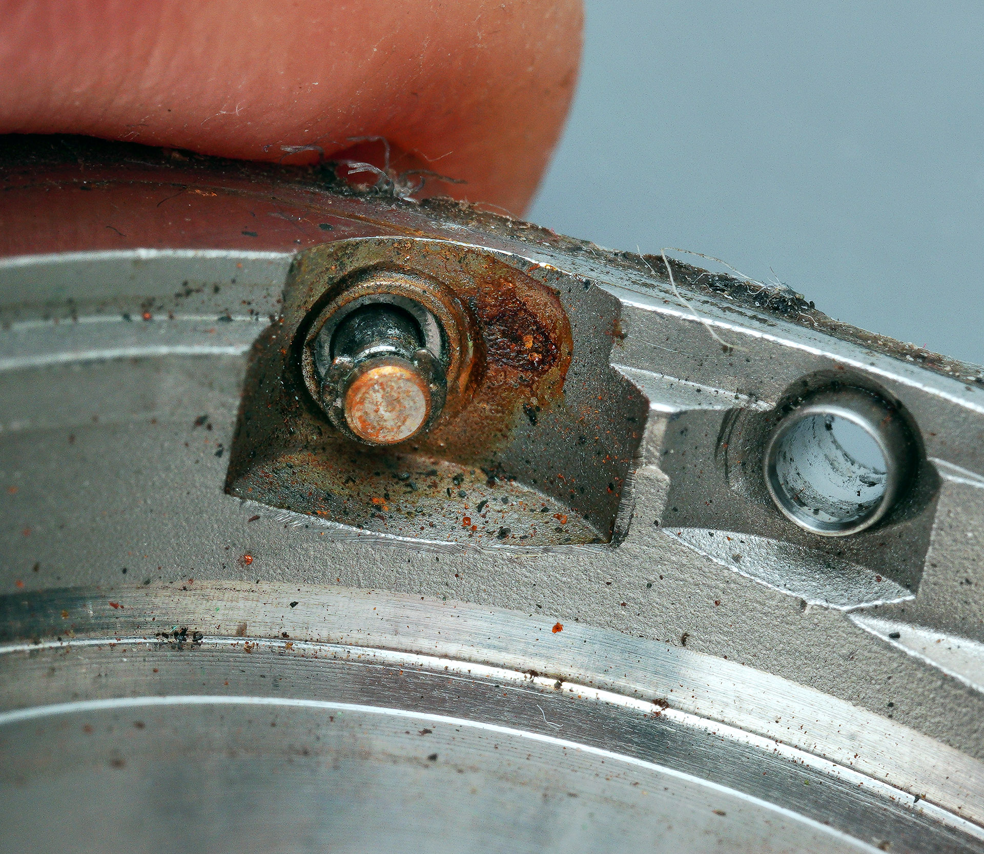
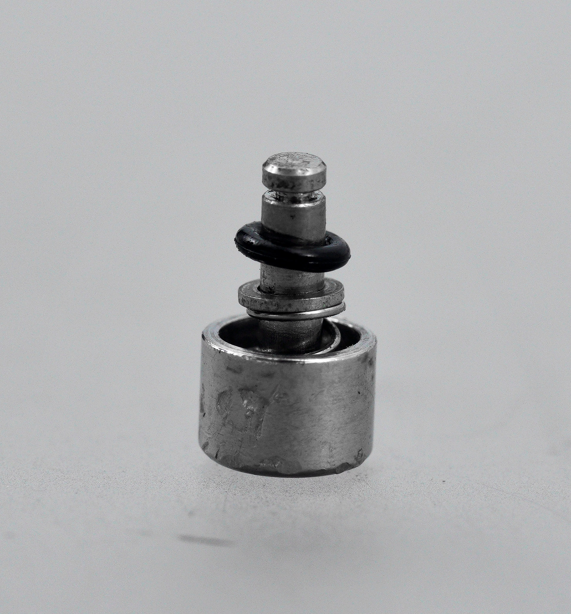
Some care is required when removing the clips because they are, after all, springs, and springs have a habit of making a bid for freedom given half a chance. The pusher assembly comprises the pusher, its spring, a washer and the circlip.

Prevention of water ingress is achieved using a rubber o-ring gasket that sits around the pusher shaft within the pusher tube in the case. The old gasket remained in the case tube when I withdrew the pusher: it is hardened and no longer fit for purpose. At this point, the mid-case, case upper and the two pushers were subject to manual cleaning with a pegwood stick, immersion in an ultrasonic bath of mild detergent, and then further manual intervention with toothbrush and toothpaste. The crown and stem had been through a cleaning cycle with the other movement parts and so were spared that ordeal.
Each pusher is reassembled by sliding onto its shaft, in order: the spring, washer and a new, lubricated gasket.
The pushers can then be inserted back into their respective case tubes and secured by refitting the circlips.
The last job before being able to reunite movement with case is to compete the assembly of the autowinding mechanism. That requires: firstly, that the second reduction wheel is secured into position (below left), its serrated edge held lightly in the claws of the pawl lever; and secondly that the winding weight is screwed to the threaded shaft at the centre of the chronograph bridge. In doing so, the arrow in the winding weight must be aligned with the hole in the first reduction wheel in order to balance the mechanism to ensure maximum winding efficiency on the wrist (I wrote a post here a while back about this peculiarity of the 70 series and descendents).
As a final touch, I replaced the rather tired original barrel and train wheel bridge holder with a new part (the gold-coloured clip at the centre of the photo below).
The movement can now be reunited with the mid-case by lowering it in from the top. There is no additional means to secure the movement within the case other than to fit the crown and stem having first fitted a fresh crown gasket.
In spite of being rather dirty, the original crystal gasket was in very good condition and so a clean in warm soapy water was all that was required to restore it to functional condition. The gasket sits snugly around the periphery of the dial.
We are two steps away from finishing the watch head: the first of these is to press into place a brand new Seiko acrylic crystal.

In addition to keeping the elements at bay and providing a window to the watch display, the crystal functions effectively as a movement retaining ring as its inner edge presses down against the edge of the dial. The pressure that it exerts is provided by the final piece of the jigsaw: the compression-fit upper case.
You will notice that at this point I have also refitted the original bracelet, cleaned and adjusted for fit. The watch is ready for action once more, bearing the patina of a life very well lived but all the more beautiful for it.

1 User usauknl1 in a post on the wristsushi watch forum here: https://wristsushi.proboards.com/thread/22232/dating-seiko-monaco-7016-evidence

Great write up there. Such a beautiful watch. Just wondering how you got the minute hand looking so much better.
Thanks Stephen! I cleaned the hands initially with it kitchen roll tightly wrapped around a pair of tweezers and lightly soaked in petroleum spirit. Just careful cleaning, avoiding the lume and then Rodico. It seems to have done the trick!
I really love that dial. Also the case construction is very unique (and a bit brutalist?).
The brutalist observation is a good one. That compression style of case seems to be a common approach in rectangular watches. The Girard-Perregaux featured elsewhere in the blog uses a similar approach albeit using screws rather than sprung latches.
Wonderful work on this classic watch.
Thank you!
Damn you Martin!
Now that I have read this article I realize how badly I want one for myself! 😜
Well, joking apart, first of all congrats for the superlative repair job and relevant documentation.
Like a good red wine or whiskey your projects appear to became better and better with time.
Being the happy owner of a 6139 since my 18th birthday, more than 50:years ago, I was familiar with Seiko chronographs but didn’t knew Seiko had produced a flyback model just a few years after they launched the 6139/6138 models.
Last night I had a look at Chrono24 and eBay to check market availability and found the 7018/7000 and 8000 series are quite common and sell for around 1000$ and the Monaco around 1500$.
Can you confirm that?
They are not cheap but I have officially started the hunt has I found the size and gracious design of these models particularly appealing.
Thank you for sharing your knowledge.
/P
Thank you very much for your appreciation! Yes, the 7018 and 7016 models seem to be quite highly valued by collectors although I am not at all dialed into where the market is right now. The Monaco models seem to be thinner on the ground, certainly in decent condition, and they also seem to have acquired a certain celebrity, although I am not entirely sure what has driven that. There are some vulnerabilities with these complex movements and if you are interested in acquiring one, then you need to be careful and certainly budget for potential repair/servicing if you plan to use the watch.
Good luck with your search!
All the best
Martin
Hi Martin. Great work, as always! I’ve felt the 70 series chronos to be superior to their 61 cousins overall, and wonder why they are both seen less often and get less love: your comments are appreciated.
What would cause a jewel to shatter like the one here?
All the Best
Tom
Hi Tom, I suspect they are less popular because they’ve not really achieved the same iconic status as some of the 61 series chronographs. The Monaco has a niche celebrity but there is not the same model diversity and so less for people to get their teeth into. As for the shattered jewel, I suspect it was contaminated/dried oil that then started to grind down the jewel and eventually it partially shattered. Or It could have been an impact perhaps.
Thanks for your comment.
Martin
Hi Martin,
thanks for another excellent post. I noticed for the mainspring you used S6 ‘braking’ grease and a small amount of 8200 on the top of the spring. I have become a little obsessed with the lubrication of mainspring barrels recently! Mainly because I cannot seem to achieve anywhere near the stated power reserve on high beat watches. Looking at info online it looks like S2 is the recommended braking grease, although these Seiko greases are not easy to come by. And a ‘small amount’ of 8200…..when you often remark on how well greased original barrels usually appear. Perhaps you could disclose your latest thinking on this slippery issue?
Michael.
Hi Michael,
Thank you for pointing out an unintentional typo! That should have read S3 for the braking grease, as recommended in the technical manual for the 7016A. I shall correct that shortly. My routine these days is to use either Kluber P125 or Seiko S3. I seem to get decent amplitude with both but then there are so many other variables.
All the best
Martin
sublime! UN Calls for Immediate Action on Plastic Pollution 2025 chic
Hi Martin,
just wondering, did you use standard hand levers to remove the stacked subdial hands? I’ve seen a couple of trashed movements and invariably the hour recording hand is most damaged. The flat of the hand is much larger than the tube to which it is affixed and I fear that hasty attempts will either damage the hand or mar the dial. What do you suggest is a safe method of attempting this?
Hi,
I cannot recall for certain, but I am pretty sure that I would have used a pair of fairly flat, wide-bladed hand levers with the hands protected by plastic film and a great deal of care! Good luck!
All the best
Martin