
Inevitably, on the lead up to Christmas, I buy too many cranberries. This year is no exception although somehow I seem to have exercised a modicum of restraint in my 600 gram haul. This quantity requires me to scale up my trusty Katie Stewart cranberry sauce recipe by a factor of two and two thirds: a somewhat obscene 470 grams of caster sugar dissolved into about 400 ml of water in a pan on the hob, followed by the cranberries. These proceed to soften and pop satisfyingly until the pectin does its job in turning the concoction into a deliciously gloopy sauce.

Those of you expecting me to take you through my hot smoked trout pate with Yorkshire pudding recipe are going to be disappointed I’m afraid. Instead, let’s take up the tale of our rag and bone Breitling, starting where we left off with a collection of cleaned parts ready to reassemble. We begin as always with the mainspring, of immaculate shape and cleanliness, ready for re-installation in its barrel.

The Valjoux 7730 is a large movement (14 ligne, 31 mm diameter), and its generous proportions are matched with a appropriately proportioned barrel. This presented the first minor obstacle to progress because my mainspring winders were not furnished with drums and arbors of the correct size. A suitable purchase later and I have the correct drum size but its arbor is too narrow. In the end, I paired the new Bergeon drum with an arbor from one of my existing sets and managed to install the cleaned mainspring without too much drama.

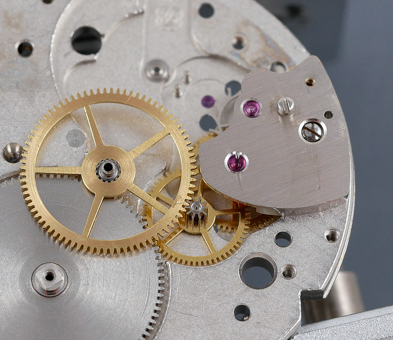
That relatively minor faff behind us and we are released to assemble the wheel train, starting with the barrel, then fourth wheel, escape and third wheels and the centre wheel.

The combined bridge secures the fourth wheel and escape wheels, the axle of the former then protruding conspicuously through its jewel, ready further down the road to receive the chronograph driving wheel.
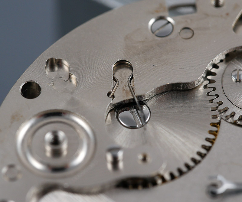
The next logical step is to secure the barrel and train wheel bridge but first we have to fit the setting lever screw.

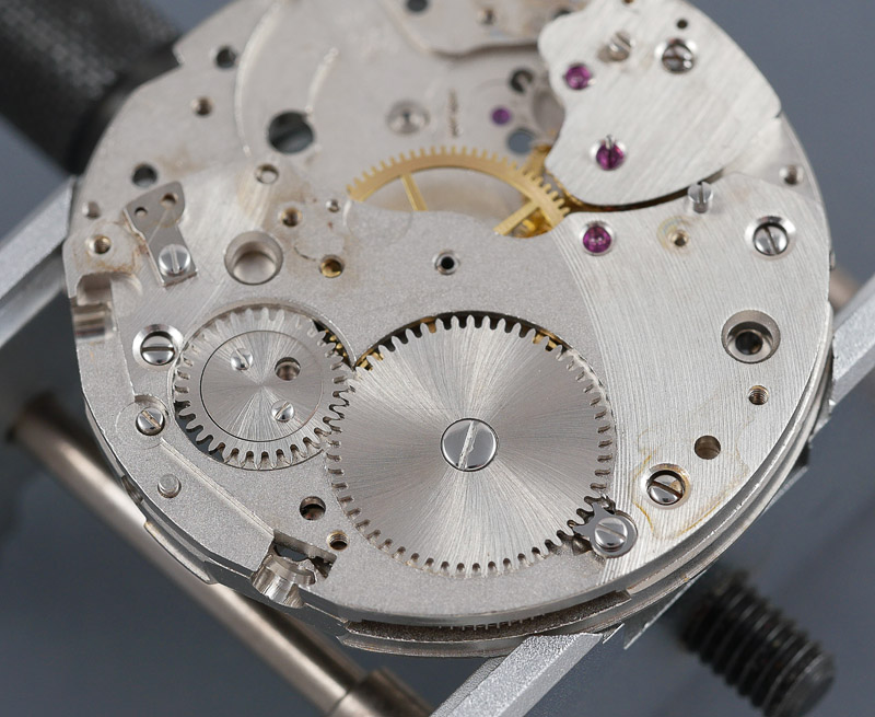
Now we can seat the train wheel bridge, taking care to make sure the wheel train beneath runs free and true before tightening it down.
The click spring and click next, with a dab of grease against the spring where it contacts the click.

The crown wheel and ratchet wheel provide the means to transfer the rotational motion from the crown and stem to the barrel and mainspring.
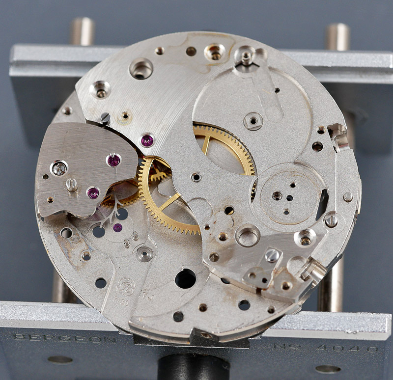
We are now ready to flip the movement over and proceed with the assembly of the dial side components. The sequence begins with the cannon pinion, followed by the clutch wheel and winding pinion (upper left and then upper right, below). The setting lever mates to the thread of the setting lever screw that we remembered to fit from the other side earlier before fitting the train wheel bridge.

The yoke and its spring come next together with the two setting wheels and the minute wheel (lower left, above). The final part of the process is to fit the setting lever spring (lower right, above). You will notice additionally that I have temporarily fitted the male part of the two-part stem and crown in order to check the operation of the setting parts.
Back to the train side and we can begin to reassemble the chronograph parts, starting with the operating lever spring.

The chronograph plate finds its place next, followed by the mounted sliding gear spring.
You will recall that the original mounted sliding gear had disassociated and so a new part is required.
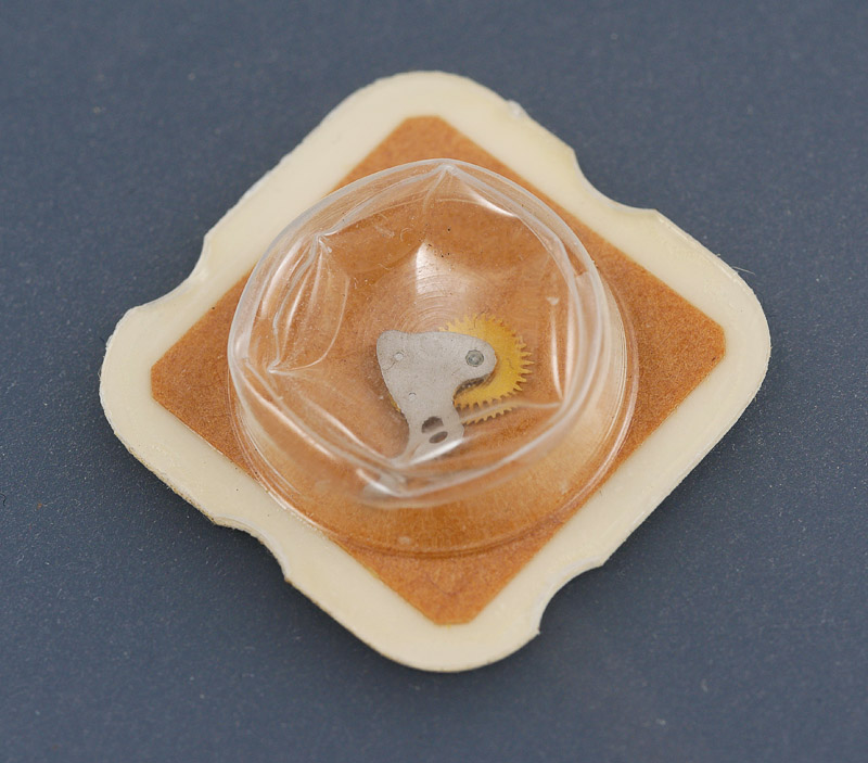
The sliding gear screws into place, followed by the minute recording runner and chronograph runner after oiling the long pivot of the latter and the contact point of the friction spring.
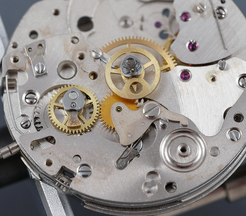
You can see in the photo above that the cam on the chronograph runner has cleaned up nicely, hopefully well enough not to impede the operation of the chronograph once the rebuild is complete. Now that the two runners are in place, we can fit the chronograph bridge.

I’ve adjusted the arm supporting the chronograph runner to sit flat once more, aware that this may throw up issues later in matching the height of the runner wheel to that of the coupling clutch. It is time now to fit the minute recording jumper, the operating and fly-back levers and the reverser. The two levers are attached to the plate using left hand-threaded screws (triple-slotted):

The reverser is the arm emerging from between the two levers, sprung against the reverser spring that sits on top of the operating lever. The double-headed hammer comes next, the role of each head to contact against the heart shaped cams sitting atop the minute and chronograph runners, returning each to their zeroed positions when the reset button is depressed.


The positions of the levers and hammer are choreographed by the tension exerted by the cam jumper against the stepped indentations on the lower tier of the hammer.

The coupling clutch plays a crucial role in transferring power from the watch train via the driving wheel to the two chronograph runners. When called upon, it swings into action against the tension offered by its spring, which you may recall was missing when the watch first came into my possession. Now that a new spring and screw have been obtained, the mounted coupling clutch can be fitted.

My earlier adjustment to the chronograph runner arm of the chronograph bridge has had the anticipated affect of lowering the height of the chronograph runner relative to that of the coupling clutch wheel, the result being that the two wheels no longer sit completely flush against each others mating surfaces.

The only means to adjust the height of the runner without recourse to bending the chronograph bridge is to adjust the position of the jewel within the arm. For this, we turn to my Seitz jeweling tool.

An appropriate anvil and pusher selected, the jewel position is adjusted by first using the micrometer screw to regulate the position of the pusher to the required height, then gently exerting pressure on the handle until the pusher makes contact with the jewel. With that done, press harder until the handle meets its stop and with luck the jewel finds itself re-positioned within its setting. Rinse and repeat until the runner sits at the desired height.

The proof of the pudding is in the eating and so we test our freshly re-positioned jewel by refitting the chronograph bridge and checking that the height of the coupling clutch wheel and the chronograph runner wheel now align (which they do).

The only remaining steps before we can test the movement and its operation are to fit the pallet fork and its cock, fit the balance and refit the two shock settings. This seemingly innocuous series of tasks edges us towards one of those moments of minor catastrophe that threaten to stop an enterprise in its tracks. I described the construction of the Breitling Shock setting earlier in Part I: we recall that the hole jewel is placed loose into the block, following which the oiled cap jewel, captured in its sprung setting, is manoeuvred into position. Here is step one completed on the dial side:

The cap jewel went in without complaint. The balance in next followed by its shock setting. Again the hole jewel into position but this time, with the balance arbor now exerting pressure on the spring, the fitting of the sprung cap proved somewhat more troublesome. Indeed, troublesome to the extent that my attentions appear to have been the straw that broke the camel’s back.

You may be able to make out that the lip surrounding the jewel is pretty chewed up, the result of past removals and re-fittings, and I suppose that those repeated actions may have fatigued the spring to the point that it let go during my exertions. I am prepared to accept the lion’s share of the blame for this one though but wherever the fault lies, the outcome is a setting that is unusable. This presents us with a real head-scratcher. These proprietary Breitling settings are simply not available from watch materials houses in the UK, Europe or the USA (to the best of my knowledge). Neither does there appear to be any other source of vintage Breitling parts available to anyone who is not already a signed up member of the secret society of vintage Breitling watch fettlers. So it would seem that we are stuck. I spent some considerable time thinking this one through. The conclusion I eventually reached was probably obvious right from the start but remember that whenever I venture into pastures new, I stumble around like a new born lamb and what might seem obvious to experienced and properly trained watchmakers takes some time to percolate through to the parts of my noggin in charge of reaching logical conclusions and prompting clear decision-making.
In the intervening period, I sought advice from two watchmaker friends, the second of whom is based in the Netherlands and who offered some prospect that a replacement part might be found but unfortunately that lead failed to bear fruit. I even tried a plaintive post on Instagram, and while that drew some encouragement and sympathy, it failed also to conjure up a miracle. And so, we come to the only logical solution to the problem: if you can’t locate part of a broken, long obsolete setting then you need to replace the shock setting in its entirety with the Swiss industry standard: Incabloc. This strategy throws up a number of questions:
- Will an Incabloc setting fit the existing balance cock?
- If I replace the Breitling shock setting on the balance side with Incabloc, will the balance staff be compatible?
- If the balance staff is compatible with Incabloc on one side, then can I leave the Breitling shock setting in position on the dial side?
The answers to these three questions appeared not to be lurking out there in the ether and so I concluded that I would need to rely on empirical means. First things first though and some research: delving into the large Incabloc catalogue of upper and lower bloc parts listed for what appears to be a pretty comprehensive collection of Swiss watch movements, past and present, I unearthed the part numbers for the complete shock unit, balance side, for the Valjoux 7730. As a precautionary measure, I ordered the main plate unit too along with spare jewels and springs for both sides.

With the shock setting in hand, I am in the position to provide the answer to question 1) above. The first step is to remove the balance and hairspring from its cock following which the shock unit is removed using a suitably sized punch from my staking set.

Eye-balling the hole left by outgoing shock unit in the balance cock (lower right in the photo above) suggests that the new part may be the right size but we won’t know for sure until I try to fit the unit. Before doing that, I run the new Incabloc setting, chaton and jewels through my cleaner to make sure they are all completely spick and span.
The shock unit presses home easy as pie, followed by the chaton and the freshly oiled cap jewel.

Satisfied that I have answered question 1) above in the affirmative, we can move on to question 2). That requires the balance wheel to be reunited with its cock and the whole shebang then fitted to the movement. Winding in some power, and away she goes.

A quick appraisal on the timing machine following some regulation suggests that the pivot of the balance staff is of the correct dimension for the new shock setting. With essentially zero beat error and amplitude north of 320 degrees, the watch appears to be perfectly content with the Incabloc substitution. The variation in performance at other positions is in line with what you might expect of a 52 year old watch movement (in fact rather better than that) and so I conclude that the movement is feeling no ill effects from having mismatched shock units (the answer to question 3)). For the moment, I am content to leave it as it is and see how things play out as the rest of the watch comes together.
This concludes part II. My aspiration for part III is to reunite the movement with its case having resolved the various issues set out at the beginning of part I. Watch this space.

Hi Martin,
First of all thank you for a great blog with VERY well written articles. Your watch skills are from my perspective outstanding. It is therapeutic reading – educational not only in terms of watch repairing, but also linguistically for people who are not native English speakers. I find myself inspired to try to make a service on a watch myself. Therefore I have a Christmas wish for a future blog post. I would very much appreciate if you could do an article on the tools you are using. What do you need for the first service as a minimum in your view?. How do you clean the parts. E.g. can I use a personal ultrasonic cleaning machine or does it have to be a special machine? What detergents must be used? What Lubricants is recommended as a minimum or is it the full set with 4 different types or more? Where do you typically find the documentation? I know it is a lot to ask and I fully respect if this is not in your interest of doing. Once again thank you for sharing these wonderful articles.
Hi Sten,
Thank you for your kind comments. Your suggestion is a good one and I will certainly make an effort to do something on tools and consumables at some point in the future. Thanks!