
Most automatic winding mechanisms employ a winding weight pivoting about a centrally-mounted bearing. In some designs, the winding weight is mounted on a separate bridge which affixes to the barrel and/or train bridges and in others, the mechanism may be integrated into the train bridge. The former approach is usually the result of the automatic winding feature being added as an evolution to an existing hand wind movement, the latter when the movement is conceived at the outset as an automatic movement. Such mechanisms are designed to convert the natural movement of the arm of the wearer into rotational motion of a weight (or rotor) which then acts upon one or more intermediate reduction wheels (or a pawl lever in the case of Seiko’s magic lever system), to rotate, incrementally, the winding wheel attached to the top of the mainspring barrel.

All of Seiko’s automatic watches, from the 17 jewel Seiko Automatic Nivaflex of 1956 via the first magic lever-equipped automatic in the Gyro Marvel, and every automatic model since, have employed a centrally-mounted rotor. Seiko’s main domestic rival, Citizen, also started off following the same path, their very earliest automatic, the Citizen Auto, an adaptation of a rather small hand-wind movement, employing a rotor mounted centrally on a separate autowinding bridge.

The Citizen Auto, however, was arguably a stop gap, released to compete with the Seiko Gyro Marvel released a year later. Behind the scenes, Citizen was working on an automatic movement that took a rather different approach inspired, perhaps, by the FHF 65 peripheral rotor ‘Fontomatic’ movement, dating from 1959.

In place of a central pivot-mounted rotor, the Fontomatic employs a peripheral rotor design in which the rotor is mounted on a circular ball-bearing rail running around the outer circumference of the movement main plate. The rotor engages with the auto-winding mechanism by means of a set of inwards-facing teeth mounted on a smaller ring attached to the rotor. Unimpeded rotation of the rotor requires a number of ball-bearings mounted within the peripheral circular rail and in some incarnations of this movement, ruby-bearings were used in place of steel ball-bearings which raised the overall jewel count to as high as 41.
Citizen introduced their take on the peripheral rotor automatic movement in October 1961 and the watches powered by this family of movements were initially marketed as the Jet and SuperJet models. All of the Jet rotor movements ran at 18000 bph but as they evolved through their six year period of production, became increasingly adorned with additional features and refinements. The first incarnation, produced from 1961, was the 0310, a simple three hand automatic fitted to the Citizen Jet Automatic. Variations of the 03 series were used, with varying levels of jeweling, in the Jet Rookie, Super Jet and Super Precision models. The 03 evolved in 1962 into the 11 series all of which were equipped with a date complication. The watches fitted with these movements were marketed as Jet Auto Dater, Super Jet Auto Dater, Parawater and Rookie with jewel counts ranging from 17 to 39. And finally the 41-series Auto Dater 7 watches were released in 1964, equipped with both date and day complications, some of which with quickset date operated by pulling the crown out from the time-setting position.

We shall see shortly how Citizen’s design differed from the Fontomatic but there are common engineering elements which suggest very strongly that the Citizen designers were guided by the Fontmelon approach.
It is time to introduce the protagonist in this tale, a Citizen Auto Dater 7, dating from October 1965, its allegiance to the Jet family indicated by the icon immediately above the central day window.

Beneath the centre hole, there are three more lines of text: the first, a solitary numeral 25, indicating the jewel count; beneath that, the number 7 embossed onto a separate applied shield, indicating that this is a watch with a day complication in addition to date; and finally the para40Mwater logo which indicates that a significant degree of water resistance has been engineered into the case.
I bought this watch on a whim because I liked the proud, downwards curve to its lugs combined with its large charismatic dial with its unusual calendar configuration, all topped off by a high-dome, albeit scuffed, acrylic crystal. The embossed shield on the case back emphasises the 7 branding, focussing attention on the day/date calendar credentials of the movement.
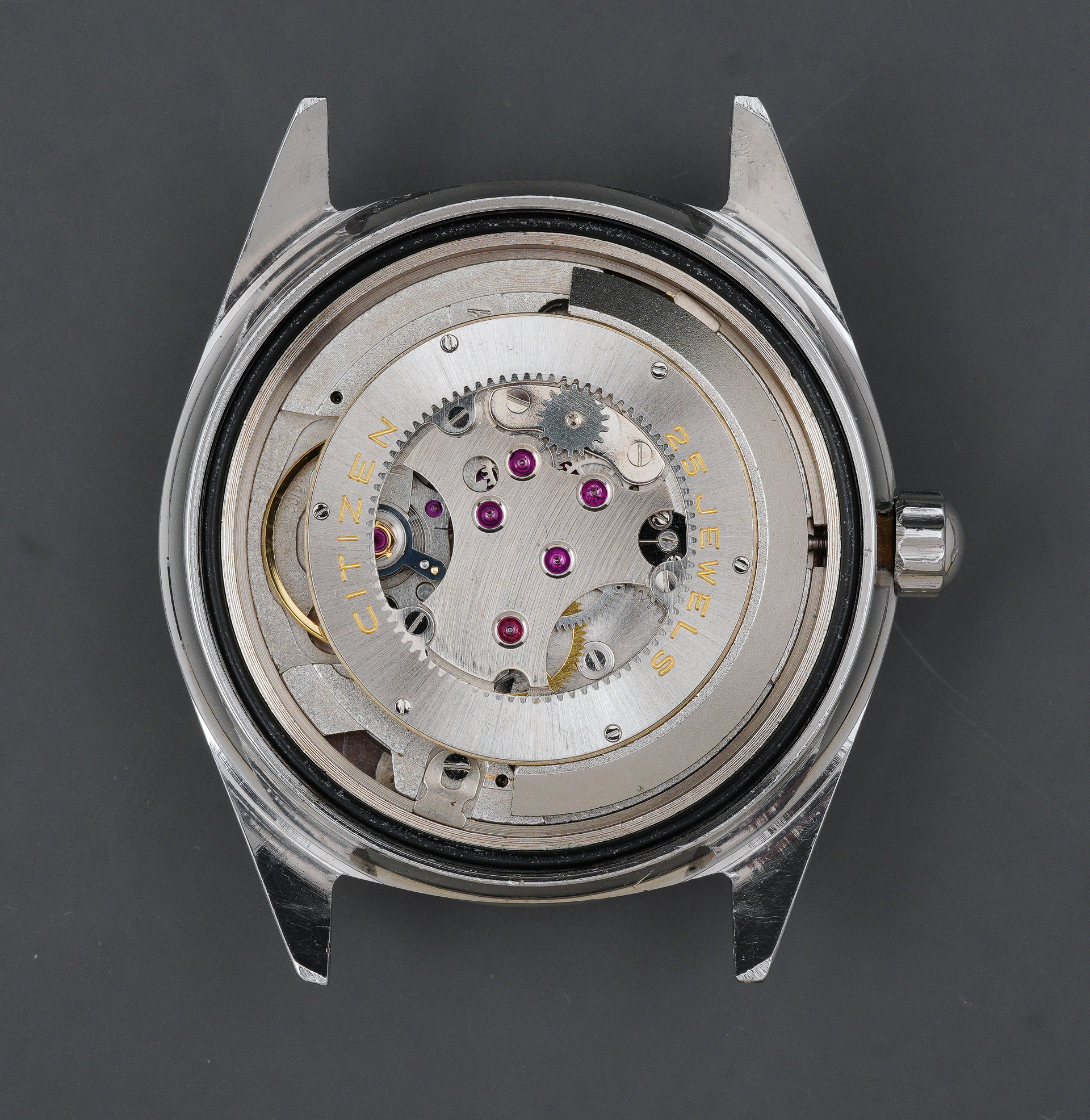
Beneath the screw-down case back sits the focus of my initial curiosity: the 25 jewel 4102 variation of the peripheral automatic Jet movement.

The first thing that strikes me, in comparing this initial view with photographs of its Fontmelon inspiration, is the similarity in general appearance but also the quite different implementation of the way in which the rotor is mounted. I confess to having had an expectation that this would be some kind of Heath Robinson implementation of an automatic winding mechanism and that the base movement beneath would be a low-rent simpleton. I could not have been further from the truth. As we dig into this one, we will discover that this is a brilliant, sophisticated and characterful movement and one which deserves recognition as one of some significance from this period of watchmaking.
Let’s make a start, the first order of business to locate the stem release button and to extract the stem.

The movement is held in place by a pair of movement clamps and screws and so these need removing before the movement can be tipped out of the case.

The dial and hands are in excellent cosmetic condition with no signs of water damage or significant degradation. However, a previous watchmaker intervention had somehow conspired to inflict a crease to the left hand side of the dial. You may be able to see this in the way the light plays off the sunburst pattern in the photo below.

Returning to the business side, we can take a closer look at the construction of the peripheral rotor assembly.

It is not immediately obvious at first glance how the different components are secured to the bridges beneath and how the rotor itself is mounted but a sensible first step would appear to be to remove the three screws mounted at 120 degrees to each other within the inner circumference of the toothed rotor. With the three screws removed, the rotor and its integrated bearing can be lifted away.

The view from the rear of the rotor reveals how the mechanism works: the integrated ring-bearing comprises three parts: an outer ring that is secured to the toothed winding weight by six small screws, an inner ring that is wedded to the outer ring by nine steel ball bearings, and which consequentially, moves independently of the outer ring; and sandwiched between the two is the inner-most steel ring with three tabs and it is this that is secured to the bridge (at the points indicated by the arrows in the photo below).

The circular bridge is held in place by three locating pins, two of which play host to the two screws that secure the reverser wheel whose role is to transmit the rotational motion of the rotor to the autowinding gears located beneath.

The autowinding mechanism employs a total of five wheels in addition to the ratchet wheel plus a sprung locking lever that works in concert with the first reduction wheel to preserve progress made by rotation of the rotor in one or other of its two directions, clockwise and anticlockwise.

You can see the long spring that works with the lever emerging from the top of the crown wheel in the photo above and more clearly below with the wheels removed. This design curiosity is shared with the Fontmelon movement.

It is time to flip her over and take a look at the calendar side.

The most conspicuous aspect of the construction on this side of the movement is that the day calendar parts are mounted on a separate calendar plate. It seems likely that this is because the original three-hander Jet movements were not designed at the outset as likely to receive a day complication further down the line. The sprung day jumper visible in the right-hand photo above is held in place by a small, dedicated plate.

Its state of precariousness with the plate removed serves as a portent of the potential difficulties that may present themselves when it comes to reassembly. I will note at this point that there are two or three such bear traps that will require a degree of lateral thinking and which suggest perhaps that the designers were not thinking as hard as they might about ease of service when designing some aspects of this movement’s core functions.
With the day calendar plate removed, the dial side of the main plate is revealed, with both setting parts and date calendar componentry on display.

Back to the gear train side and we can get a better sense of the essential layout of the movement.

The three bridges, barrel, train and balance (cock) are arranged in a neat circle. We can note three things in particular: the barrel arbor hole in the barrel bridge has been closed up by a previous watchmaker to reduce side shake from an ovalised hole; the train bridge is fully jeweled; and the balance cock does not benefit from an adjustable stud holder which means that any beat error can only be corrected by rotating the hairspring on the balance staff. Removing all three bridges reveals the underlying simplicity of the gear train: the barrel, centre wheel, escape wheel, third and fourth wheels. That’s it.

A sign of a previously clumsy intervention is the condition of the pallet cock which appears to have been bent, presumably from a lever action exerted by the watchmaker when removing it at service.

I resolve to source a replacement although it is not yet clear whether this damage will have any material effect on the operation of the movement. Back once more to the dial side to dismantle the setting parts.

There is an additional complication here in the quickset mechanism, operated by pulling the crown out from the time-setting position. This necessitates the inclusion of the lever and spring that are concealed by the long plate that extends over a significant arc (left, above, in place; right, above, removed, exposing the spring and lever).
The final task before we can declare the disassembly complete is to remove the mainspring. In situ, it is caked in similar levels of molybdenum grease as is typical of Seiko movements of this period. It is also worth noting that it is wound in clockwise which means that in theory I will need a left-handed mainspring winder (but I have means to get around that hypothetical requirement).

Extracted, it looks in fine fettle, flat and still with plenty of spring in its step.

While the movement parts percolate, fizz and swirl, I turn my attention to the casing parts. The midcase, bezel and caseback just require the usual attention from pegwood, toothbrush and a spot of Colgate.

The crown on the other hand, needs a reasonably serious degree of intervention if it is going to be able to contribute to the delivery of 40m–worth of water resistance.

At the point I’d taken this photo, I had already extracted the gasket and had met no resistance at all from the securing washer because, as you may be able to discern, it was in no fit state to do so. I spent some time attempting to fashion a replacement washer before abandoning that endeavour and instead opted to use an identical crown with a washer in good condition farmed from a parts watch. Before rebuilding the cleaned crown, I identified as close a match as I could to the original gasket.

Obviously, the one going back is not the one on the right. The following tetraptych shows the four stages of reconstruction: cleaned crown, plastic spacer, well-lubed gasket, securing washer, sealed round its edge with a light film of Loctite retaining compound.

Back to the movement and we can begin reassembly, starting with that lefty-loosey mainspring. My mainspring winder is right-handed but generally works quite well if you load the spring back-to-front and wind in anticlockwise.

This movement has no capped settings and so we can jump right in with the setting parts, starting with the stem, clutch wheel and stem release button, followed by the yoke and its spring and then the setting lever (clockwise from top left in the photo below).

The pull-out quickset lever and spring comes next. This was a bit of a pig to fit and required a little fancy footwork to get the spring to stay put while fastening down the cover plate.

Back to the balance side and we can begin the process of assembling the gear train, starting with the centre wheel and its bridge followed by the assembled barrel and then the escape, third and fourth wheels. The barrel bridge comes next and then the separate train bridge.

The very elegantly-shaped click, ratchet wheel and crown wheel come next, all looking very refined.

We are getting very close now to being able to kick some life back into the movement and seeing how she runs. The four steps to get us there are the fitting of the pallet and its cock, with the pallet stones then lubricated in situ, the balance and its cock, swiftly followed by the two-component proprietary Citizen Parashock shock protection system.

The movement was running by step two and with a full wind under its belt and a moment or two to settle, we can take an initial measure of the timing.

I’m not bothered by the rate because that is easily adjusted, and the traces are very clean which bodes very well but the beat error is pretty bad. Normally this wouldn’t be a problem but this movement does not benefit from a moveable stud holder and the only way to adjust beat error is by trial-and-error adjustments to the hairspring collet to rotate incrementally the hairspring around the staff.

This can be a tortuous process because it is so easy to overshoot one way or the other. Eventually I managed to reduce the beat error to a satisfactory degree.

Unfortunately, in the crown-down position, the timing went to pot, with the movement now running slow.

I tried all sorts of approaches to eliminate this issue but was unable to do so to my satisfaction. In the end, I resorted to fitting a replacement balance wheel from a spare parts watch and that solved the problem. Inevitably though, the beat error was back and so I had to go through another round of hairspring collet tweaking to get everything properly timed and performing well in all positions.

With the movement running well, we can flip once more to the dial side and install all the calendar components.

This begins with the date driving wheels, the date jumper and its spring plus the date disk. This is all secured into position with the separate day calendar plate (top right, above), before installing the day driving wheel, the day jumper and its spring, secured under its own guard (a fiddle), and finally the day disk with its film washer. That lot is all held in position beneath the spruced-up dial.

The lighting in the photo above reveals the crease about two thirds of the way from the centre hole in an arc between the seven and ten markers. A side view shows the dial tilt more clearly.

The one remaining significant task is to reconstruct the automatic mechanism. At its heart sits a curious design element whose odd-ball appearance belies the elegance of much of the rest of the design of this likeable movement. The transfer of energy from the rotor via the reverser wheel mechanism to the reduction wheels and beyond is regulated by a sprung lever. The linear spring that acts upon it extends all the way from the centre of the crown wheel, from where it pivots, across the full width of the train wheel bridge and extends beyond even that to mid-way between the edge of the bridge and the centre of the balance wheel.

Initially, it is not immediately obvious how the spring gains purchase on the lever. In the photograph above, it is not doing so because it is not yet correctly located. What we cannot see from this bird’s eye view is that the elbow of the lever is slotted and the spring must locate into the slot. The tension can be adjusted by turning the slotted pivot at the centre of the crown wheel.

The complete autowinder gear train can be placed into position next.

Without the rotor for context, and with one other crucial component missing, it is difficult at this stage to see how any of these wheels might talk to the rotor. With the bridge fitted, we are one step closer to seeing the light.

If we look a little closer, we can see better that the role of that sprung lever is to prevent the first reduction wheel from reversing direction during the transitions of the reverser.

The bridge at this point is just located on the three dowels and not yet properly secured to the bridges beneath. We accomplish that security by fitting first the rotor and then the reverser mechanism.

The autowinding bridge is fastened to the train wheel bridge by three screws: the two screws that also secure the reverser mechanism and one of the three screws that secure the rotor to the autowinding bridge. The screw adjacent to the balance wheel is longer than the other two screws for that reason.
With that all done and tested, we can refit the hands and survey the completed movement from the dial side before readying the case.

When we last met the mid-case, it looked like this.

Aside from an accumulation of grime and light corrosion to the mating surfaces between case-upper and the bezel, the case is in very good cosmetic shape. After a clean the case is looking a little more presentable.

An initial assessment of the watch as received might have suggested that the watch either used a separate polished rehaut or employed an armoured acrylic crystal with a polished tension ring. However, as can be seen in the photograph above, the rehaut is an integrated part of the case and forms a lip around which the crystal sits.

The water resistant seal is then achieved from the clamping force exerted by the external bezel, pressed into place using a crystal press.

With that job done, the case is ready to receive the movement.
This rather eccentric creation has one final curve ball for me and that lies in its dimensions: the lug width is an uncommon 21 mm and needless to say I have no straps of that width available to fit to the watch. However, after an extended rummage I came up trumps with a generously-sized 20mm strap that I had used for a short while with my Rolex DateJust many years ago. In situ, I think it suits this watch rather well.

My recent diversification into the world of the vintage Citizen has opened up new vistas of discovery. Citizen watches from this era offer their own very unique personality. Their designs are often quirky and off-the-beaten track.

The design and engineering of their movements is refreshingly different and provides an opportunity to surf a little outside of my comfort zone into territories that provide new opportunities to learn.

This particular watch is really rather wonderful. Its size seems completely out of keeping with the trends of the time and its left-field approach to the implementation of its perpetual winding is a delight. Although in use, that mechanism is hidden behind the solid steel caseback, the wearer is always aware of its presence because of its conspicuous whirring soundtrack as the rotor makes its way hither and thither around the inside track of its circular monorail bearing.


An excellent write up as always Martin, thank you for taking the time. And a very timely one, I have a Jet on the shelf waiting for me to get to it (people keep queue jumping meaning my own little projects get bounced). I will be reading this a few times before I start the reassembly.
Thanks Pip. Good luck with yours when you put it back together.
Another great restoration. I was wondering about your experience wearing it. I have two Citizen Jets and I find that they require more vigorous movement to get the rotor swinging. Occasionally, if I spend too much time in a day on the computer, for example, it won’t keep up and the watch will run out. I have never had this happen with more traditionally rotored automatics. It occurred to me that the ‘Jet sound’ might represent additional friction that this particular automatic system inherently has.
Brian
Hi Brian, mine seems to spin with gay abandon, whizzing around loudly and proudly. I’ve been wearing mine for the last few days and had no problems at all with it building up sufficient power reserve. Have yours been serviced recently?
Well, I did. But perhaps it requires someone a little more versed in these movements. Let me know if you find it ever fails to keep itself wound. I would be interested. I figured that was one reason they abandoned the Jet movements.