
For ten years, watch-parts-cleaning duties have fallen to my trusty Indian-made Pearl-branded watch cleaning machine, a clone of the Elma Super Elite. Just as with the Elma original, the Pearl is equipped with a variable-speed, reversible motor, three jar apertures (one cleaning, two rinsing) and a heated drying chamber. It has been utterly reliable during my ownership but its operation is completely manual, with no options for any kind of automatic tailoring of the cleaning cycles.

A year or so ago, I started to think about upgrading to something a little more modern but without pushing the boat out in terms of expense: I am not a full-time watchmaker and did not need a fully automatic set-up; I just wanted something that offered the prospect of, say, automatic direction switching and some tailoring options for rotation speed and acceleration in the cleaning, spin-off and drying cycles. Having seen the cost of a new Elma machine from Cousins, and as my thoughts turned to other left-field options, I happened upon a self-build watch cleaner project at diywatchcleaner.com. The developer of that project had initially floated the concept as part of a Kickstarter campaign but I did not stumble over it until a year or so after it had reached its funding target.
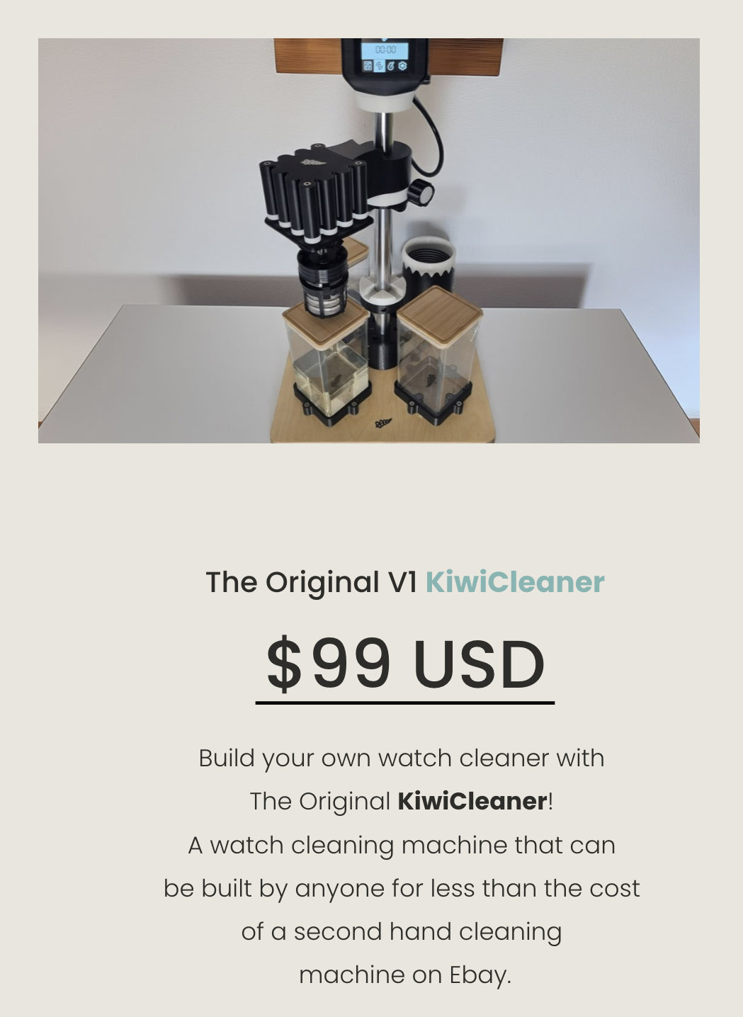
The basic premise involves an initial purchase of a build manual which includes a bill of materials for the critical components and hardware and the 3d-printing files required to print the various 3d-printed parts. The links for most of the main components take you to sellers on AliExpress but the hardware (screws, nuts and bolts), the jars and the wooden base need to be sourced locally. I should also note that the build is considerably eased if you opt to source the control board and display components directly from the site owner which is what I did.
I signed up almost a year ago (May 2024) and once I’d received the build manual, I placed my orders for the core components from AliExpress, the control board and display from diywatchcleaner.com and the baseboard and most of the hardware from sources in the UK. There was also the small matter of the 3d-printer, which up to this point was nothing more than a hypothetical. The usual round of fevered late-middle-aged man research resulted in the purchase of a Bambu Lab A1 printer together with two reels of PETG filament.
I started the build in June 2024 by taking delivery of an unsealed 390 x 390 mm steamed beech veneered MDF base board and sealing it in several coats of clear satin varnish. That having been done, I then proceeded to do nothing at all, not even open the 3d-printer box until March of this year. Opening the package from Bambu Labs was therefore the catalyst to getting the project proper underway.
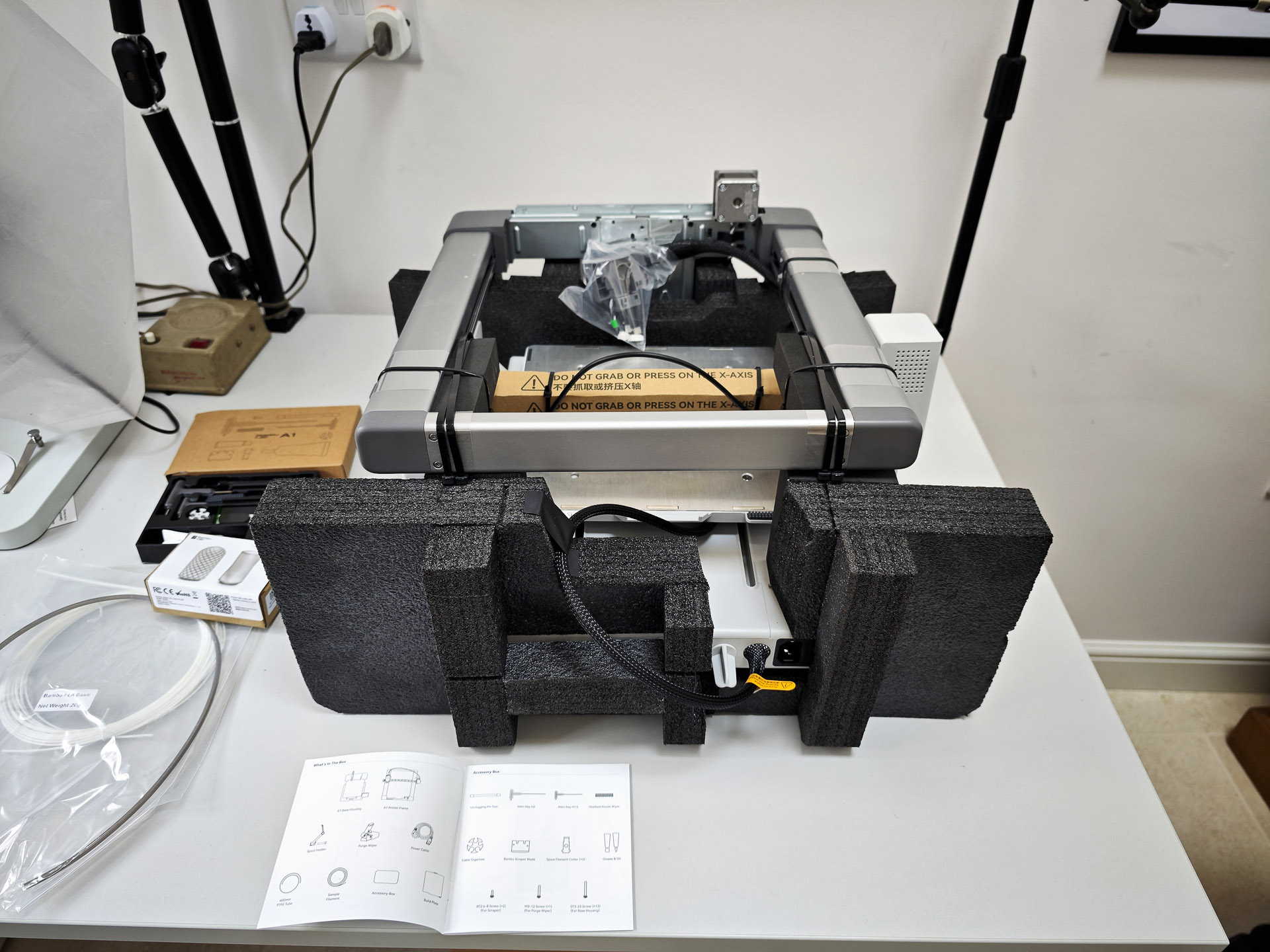
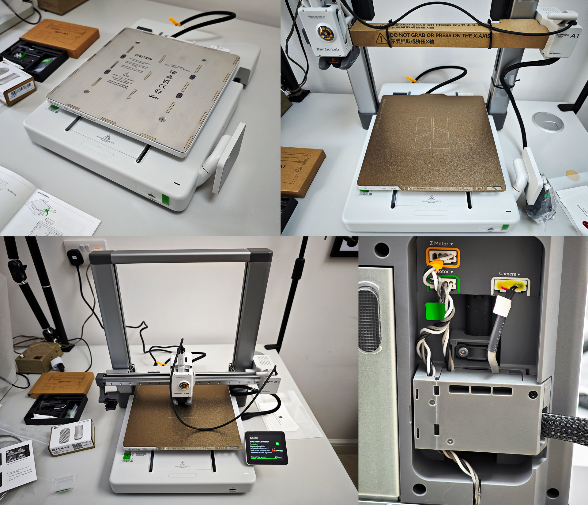
I’ll spare you the details of the printer assembly other than to observe that it is reasonably involved but straightforward if you follow the instructions carefully.
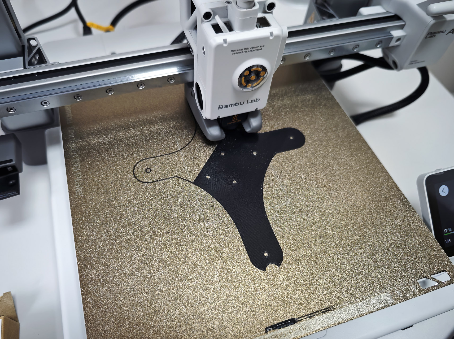
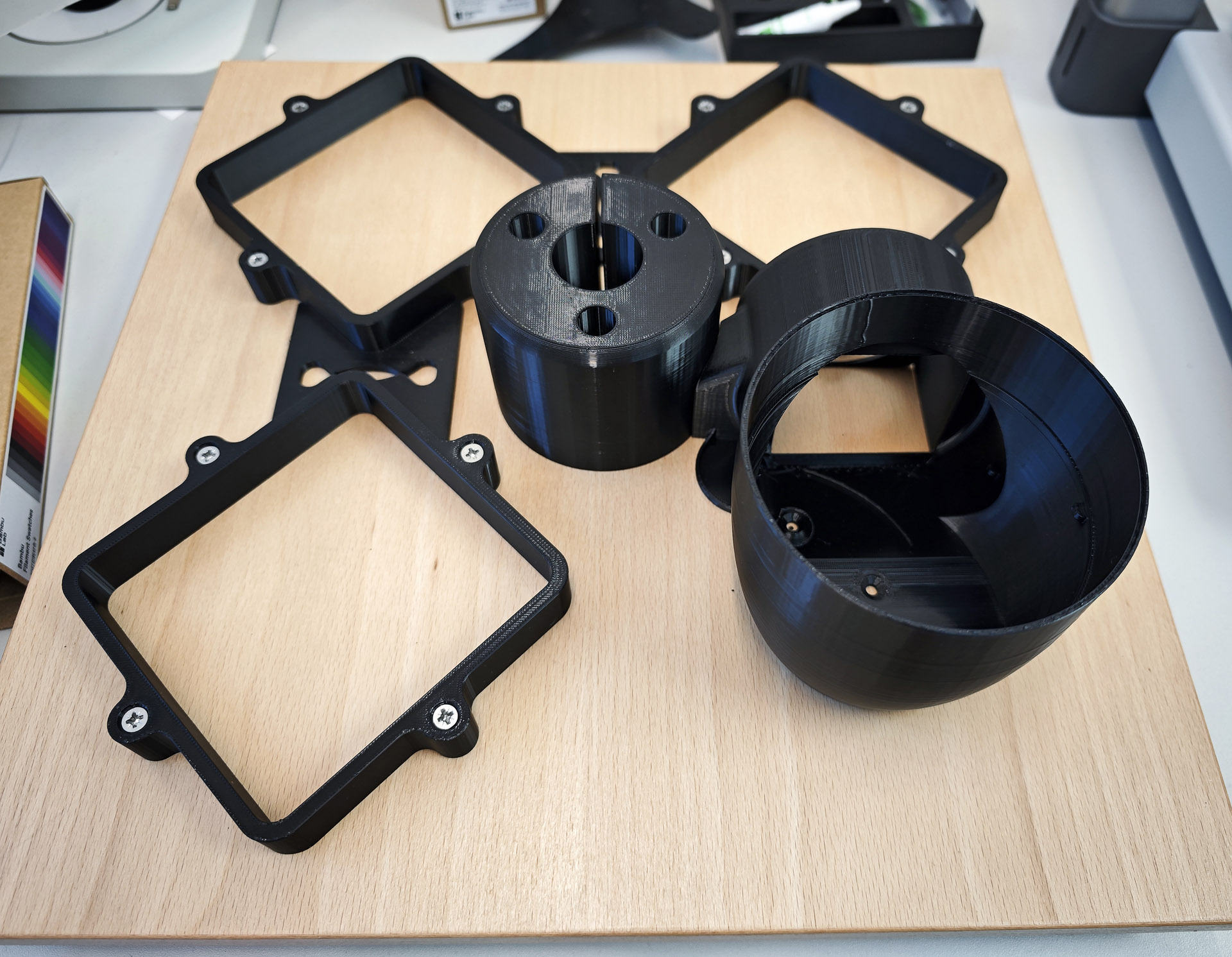
Test print complete and we can move along to page 10 of the build manual. The first order of business is to choose the jar size and shape because this choice determines some of the critical dimensions of the build. I had initially bought a set of slightly over-large square-based biscotti jars but the size of their mouths was too small to accommodate the cleaning baskets and claw. A rethink and I ended up opting for a set of smaller, square based jars from, of all places, Poundland, at extremely modest expense. With that choice made, the first print job is of a template which will be used to determine the position of the three jar holders and the drying chamber.
The template is positioned at the centre of the board and the holes then used for pilot-holes for the base clamp, heater base and the three jar holders.

With that done, the template can be discarded and the centre hole drilled out using a spade drill.

The three (now printed) jar holders are attached via one of their pilot holes and positioned with the aid of two spacers.

The spacers allow the nine remaining pilot holes to be drilled to accommodate the three remaining screws for each of the three jar holders. Next, four feet are printed and attached at each of the four corners on the underside.

The centre clamp and heater base are printed next, with only the former attached at this stage to the baseboard.
Fitting the 500 mm long 30mm stainless steel rod into the base clamp somehow transforms this into something approximating what we are aiming for.

The two parts of the lower clamp are printed and joined.
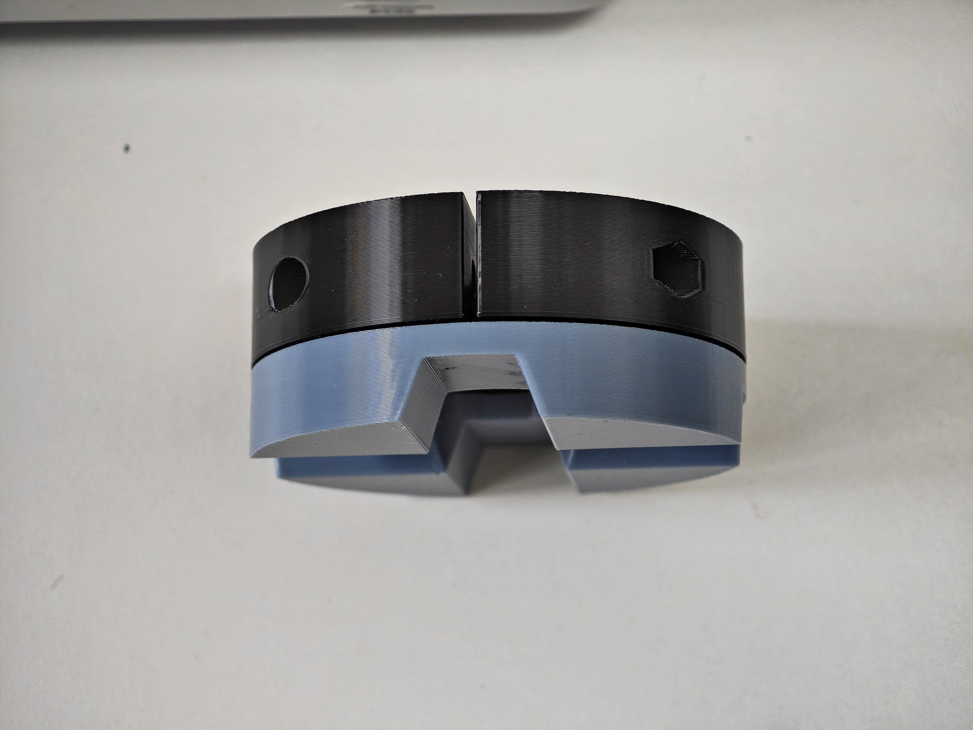
This clamp is fitted into a temporary position on the central rod where it can wait while we print the largest (and as it turns out) most problematic part of the exercise: the boss.

The boss will in due course support the motor bracket with the motor wiring threading through from the rectangular hole at the front to the central circular hole at its other end. When 3d-printing parts with cavities, it is common practice to specify a support to prevent the freshly laid hot filament from collapsing into the voids. Stupidly, I failed to read the instructions for this part correctly and printed it initially with supports specified. However, the elongated path taken by the channel required for the wiring is such that it proves impossible to remove the support and so the first attempt is consigned to the waste pile and I print it again but with supports unticked! Here’s take 2, with the motor wiring successfully threaded through the channel.

The motor wiring needs to be extended and this is achieved by soldering the four wires in the motor loom to four cores in a length of four-core electrical cable.

I trimmed the motor wiring to a length that would allow the connector to reach over the motor to its connector, with the end of the extension cable insulation sitting just inside the hole in the end of the boss. The length of this extension will be determined towards the end of the build as the overall wiring routing takes shape.
The top clamp and knob are printed next. These parts will combine with a wavy partner which will mesh with the lower wavy at the top of the lower clamp.

The upper clamp is screwed to the base of the boss and the whole assembly fitted to the 30 mm rod.

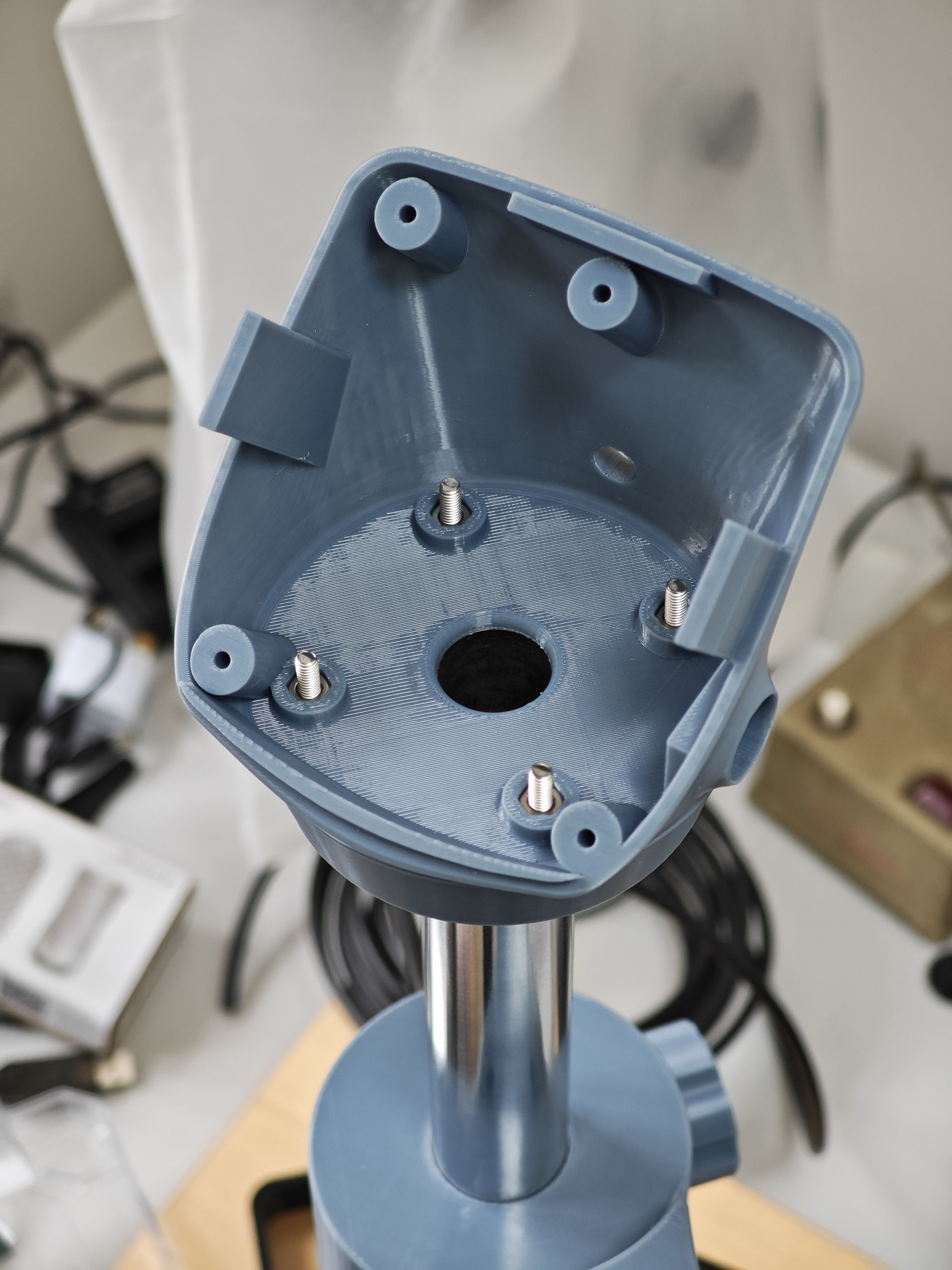
We move next to the computer housing, starting with the lower part which sits around a 30mm metal collar.

The upper computer housing sits on top of this lower collar, secured by four bolts.
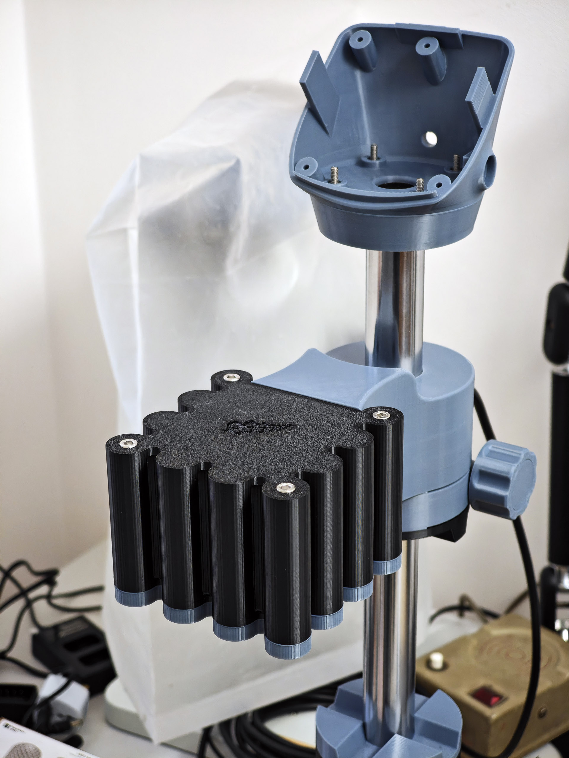
Let’s pause at this point to take in the bomb-site but reflect on the progress being made.

You may have observed in the photo above that I’ve attached the motor bracket to the boss. The motor housing base together with four nut holders can be seen towards the bottom right-hand-side of the photo. The base sits beneath the lower part of the bracket and the four nut holders nestle into the four recesses in each corner of the motor base.

Connecting the motor loom to its connector allows us to fit the upper part of the motor housing.
The next stage was probably the trickiest, requiring very careful measurement of the motor shaft before cutting it to length to ensure that the cleaning basket sits an inch or two above the base of the jar. I ended up extending the ‘measure twice, cut once’ principle to ‘measure thrice cut twice’ to good effect.

It is worth observing that cutting through stainless steel with a fine-toothed hacksaw is very hard work. It’s even harder when you end up having to do so twice (bottom right, above)!
The drying chamber comprises four components: the heater complete with fan, the 3d-printed heater base, an 8 oz can, previously occupied by tomatillos, and the heater shroud top (printed). These come together more or less as shown below:

The organisation of the wiring is the responsibility of the builder and you can see my approach in the photo below:
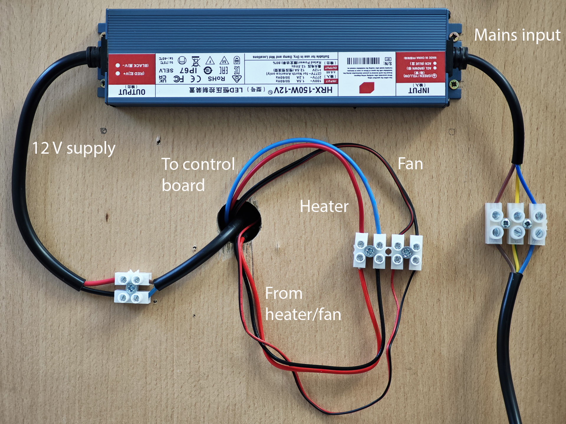
The wiring from the heater is routed through the hole in the wooden base and then connected to the extension wiring which finds its way up the 30 mm central tube to the control unit at the top. The wiring is all selected to handle more than the anticipated maximum current load. The mains input connects to the 150W 12 V power supply which is fixed to the base of the board and the 12 V output connected to a 13A-rated extension lead that feeds up the tube, also to the control board. For additional safety, I covered the connector blocks feeding the mains supply with a plastic cover.

The mains input is switched using a heavy duty mains switch, modified to provide an earthing bypass.

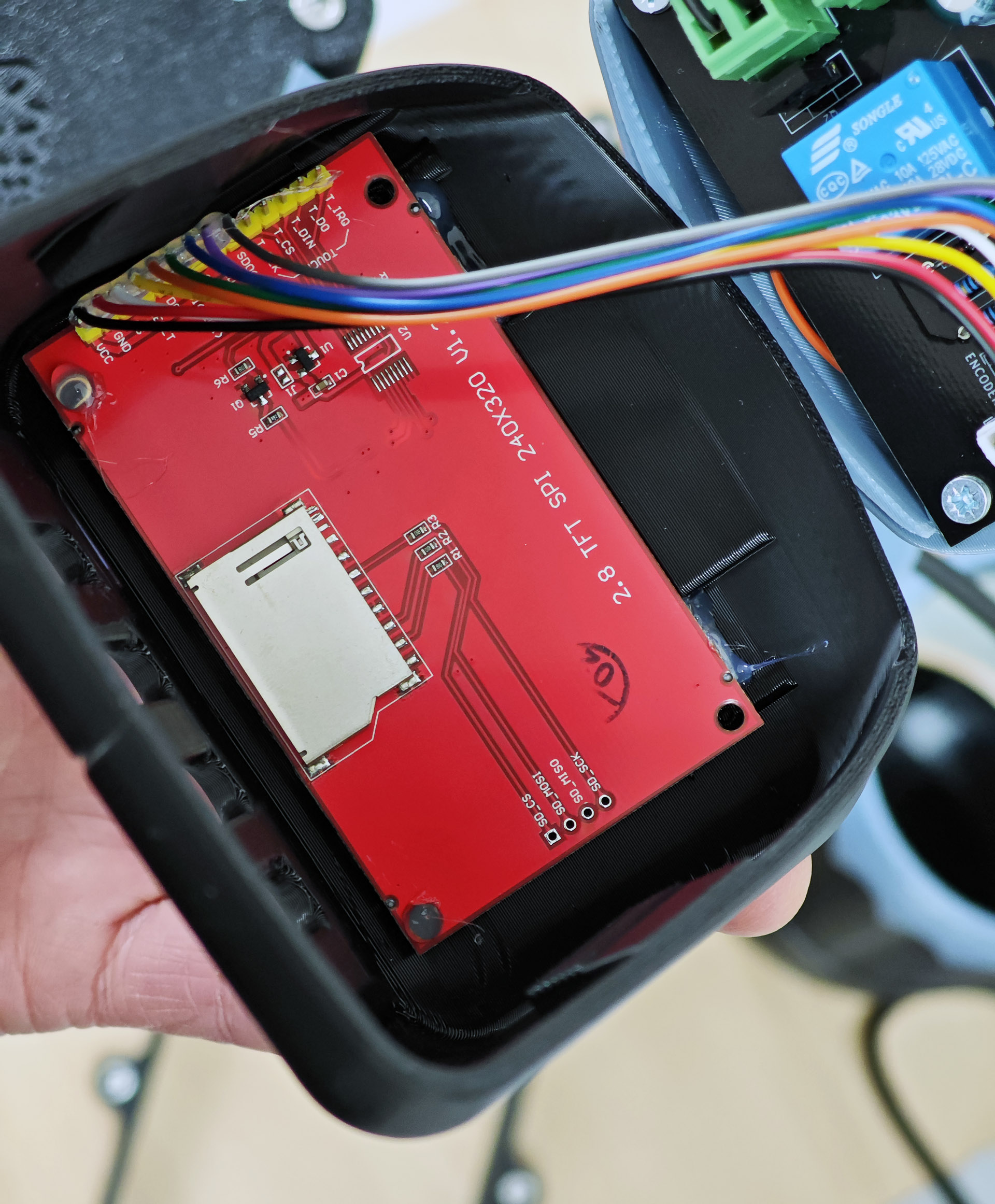
The final steps all concern the wiring of the various electrical components to the Kiwiboard controller. The first of these is to fit the encoder knob into the hole in the computer housing, securing it with a squirt of hot glue. The board itself is placed loosely into position and the wires from the power supply, heater, fan and motor trimmed to length and connected to the board. Considerable care is required in connecting the motor because of the changes in wire colour between those on the motor loom, those in my chosen extension lead and the colours given in the manual! The encoder knob is connected to the rear of the board and the screen to the top.

The screen is tested and then hot-glued into position in the top part of the computer housing.
The final step is to complete the computer housing assembly and then run the machine through its paces.

This was a somewhat daunting undertaking, one that certainly tested my comfort zones at times but which has also undoubtedly expanded my horizons. The end result, at least at the time of writing, is an unqualified success. It operates beautifully and has been put to the test on a Breitling Top Time project about which you can read more on Instagram, and possibly at some point here. In the meantime, please see the video below, showing the machine in action.
Acknowledgement: I’d like to thank Frank at diywatchcleaner.com for making his design available to the watchmaking community and for his friendly and very helpful responses to my initial enquiry.

That looks like a very clean set-up. I am assuming from the look of the design that you need to manually move the arm between jars similar to my old faithful Brenray (with a blown heater so I have to use a hair dryer)
Yes, you have to move the boss between jars manually. There is now a fully automatic version available but of course that costs quite a bit more to build. I’m quite content with this approach for now.
WOW! I was impressed!
Dan Samson
Vancouver Island
Thank you very much for this post! I have been looking for a cleaning machine for a while and I am very excited to try this myself too.
The only thing is that I might end up paying the same as a brand new Pearl Sona sold on the web (around 650usd+ shipping maybe 750usd in total) and this is if I managed to 3D print somewhere else (so avoiding the purchase of a 3D printer).
What would you say is the advantage of this cleaning machine over the Pearl Sona that you used to have. You mentioned more control of speed. In general do you feel it perform better than the Pearl Sona? Anything else over the Pearl Sona ?
I love the idea and this machine looks way better too!
Thank you!
Hi Jerome,
I’ve not totted up the complete cost for me and of course I also bought the 3d-printer as part of the exercise but that will and has already been very useful in other respects. Probably the main functional difference is the control you have in being able to program the speed, acceleration, and directions changes and frequency during the wash and rinse cycles as well as spin off. The heater is also very gentle and incorporates a fan. No need to remove pallet forks during the drying cycle. I would say also that the whole process was just very enjoyable and that provided considerable added value. I’ve ended up with a machine that is functionally very similar to an Elma Solvex SE but at about a fifth of the cost.
Thank you! Merci beaucoup!
PS : I definitely like more the modern look of this cleaning machine.
Does having a 3D printer mean you never have to buy a movement holder again? You could print one for every type of movement you work on!
Hi Brian,
Yes, I’ve already printed a few movement holders as well as several other watch tools. It’s a really positive addition!