
We have reached the end of the beginning, the point at which the summit has been reached but the mountain is far from conquered. The descent will be a great deal more challenging, not to mention more hazardous, than the ascent but as with any significant task, it’s best achieved step by step. Let’s not worry just yet about reaching base camp in one piece when we have a little time to stretch our legs and contemplate.
I want at this point to take a moment to consider the aspect of this project that has had the most upsetting and destructive impact on the outcome: the widespread oil contamination. As we have seen, the main areas of concern are the outward-facing printed parts: the two lap-counter disks, the dial itself and the tachymeter ring. All four of these components were saturated in oil, the dial affected the least, the tachymeter ring and counter disks the most. Let’s consider first that tachymeter ring. Here it is in situ.
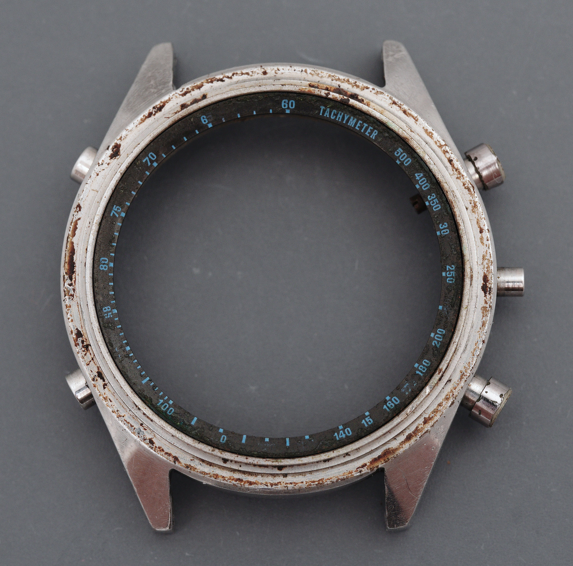
At this distance, it presents as pretty grotty but with the print largely intact, apart from some areas where the numbers have been either partially or wholly erased. A closer view, however, reveals a much clearer perspective on the devastation.
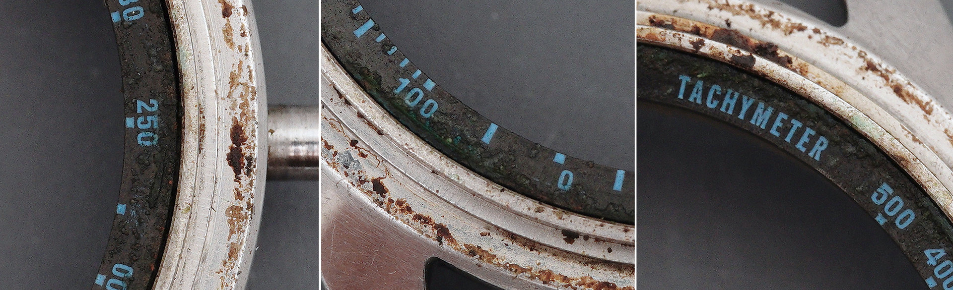
The ring is caked in semi-solidified deposits of oil across its whole surface but the worst aspect of this was only revealed to me when I made a tentative attempt at cleaning some of the oil away: virtually all of the print has been liquified by or dissolved into the oil. It still has the appearance of its original form, more or less, but any contact at all with the tip of a piece of Rodico, or cotton swap or errant finger and it smears away. I found myself impaled on the horns of a dilemma: clean the ring and lose some or all of the print or refit a heavily contaminated part to an otherwise restored watch (assuming we ever get to the end of this mammoth undertaking).
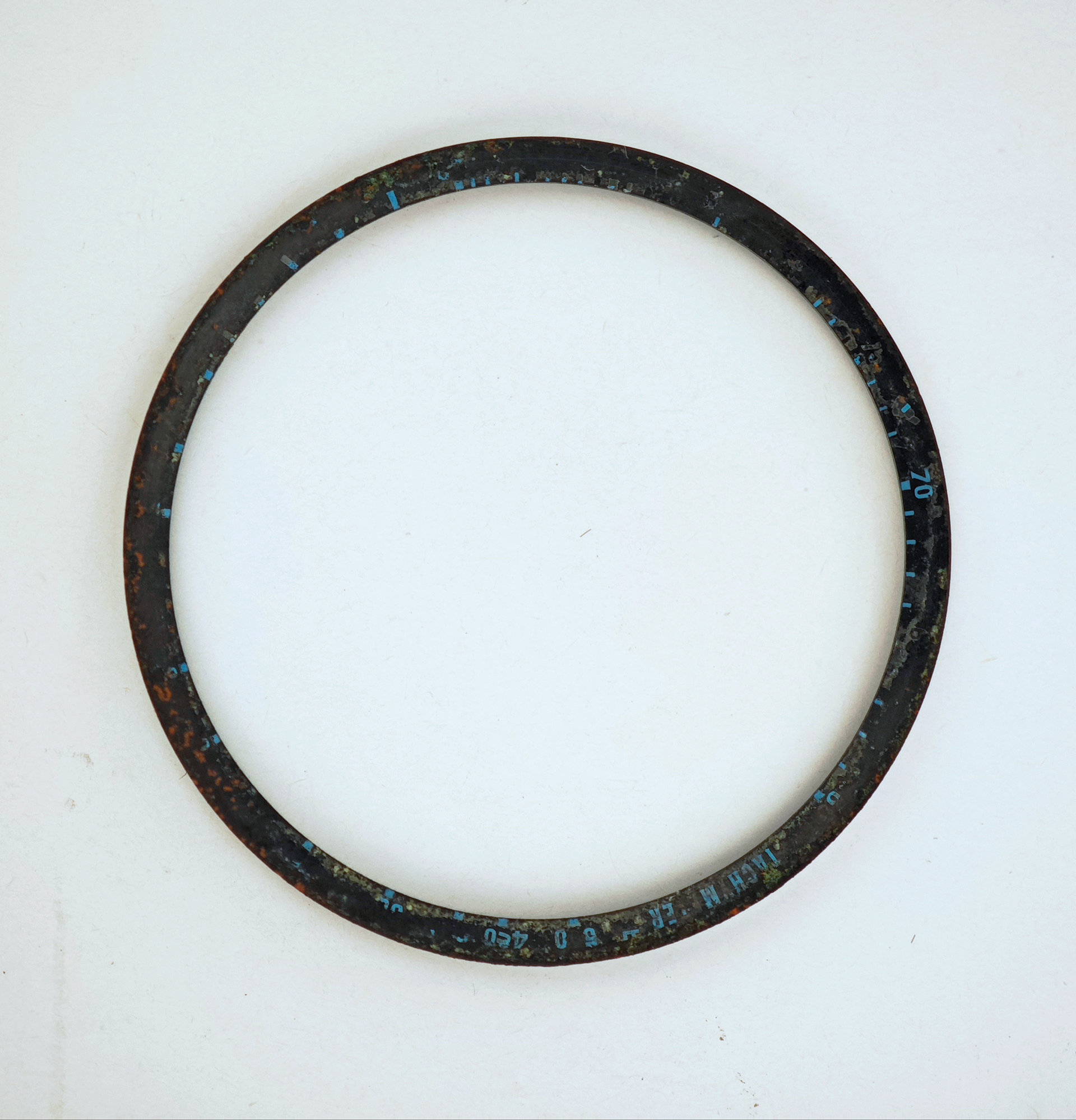
I presented the issue to the owner and he quickly came back with a preference to clean the parts that had been contaminated with oil. This would have been my inclination too and so my thinking turned towards seeing if there might a way to remove the oil without affecting the print. I considered all of the organic solvents at my disposal but the most benign of these seemed to have little impact on out-of-sight test areas or were far too aggressive. The irresistible reality was that the oil and the print had become one and the same: there was no separating them. With that realisation landing, it became clear that the focus should be on removing the oil but not inflicting further damage on the underlying fabric of the ring itself. The route to achieving that could be to move away from organic solvents to something more benign and universal: water. I knew that dipping the ring into a water bath would have no impact on the oil but what about a momentary exposure to a light solution of water and a drop or two of detergent in my ultrasonic bath? A half second dip later and I had my answer: most of the oil but also most of the print disappeared in a puff.
Was this the sharper or blunter of the two horns? If the ring had been refitted without cleaning, then some measure of its function would have been preserved but the integrity of the print would remain a complete illusion. To have refitted that part as it was would have gone against all of my natural instincts but nevertheless, the result still feels like a defeat. I don’t have a high-quality photo of the immediate after-effects but here’s a shot taken on my phone which conveys the outcome well enough.
There is still some work to do with the ring because in some areas the oil had eaten through the black anodised surface, with copper leeching from the brass and presenting as brown areas resembling rust.
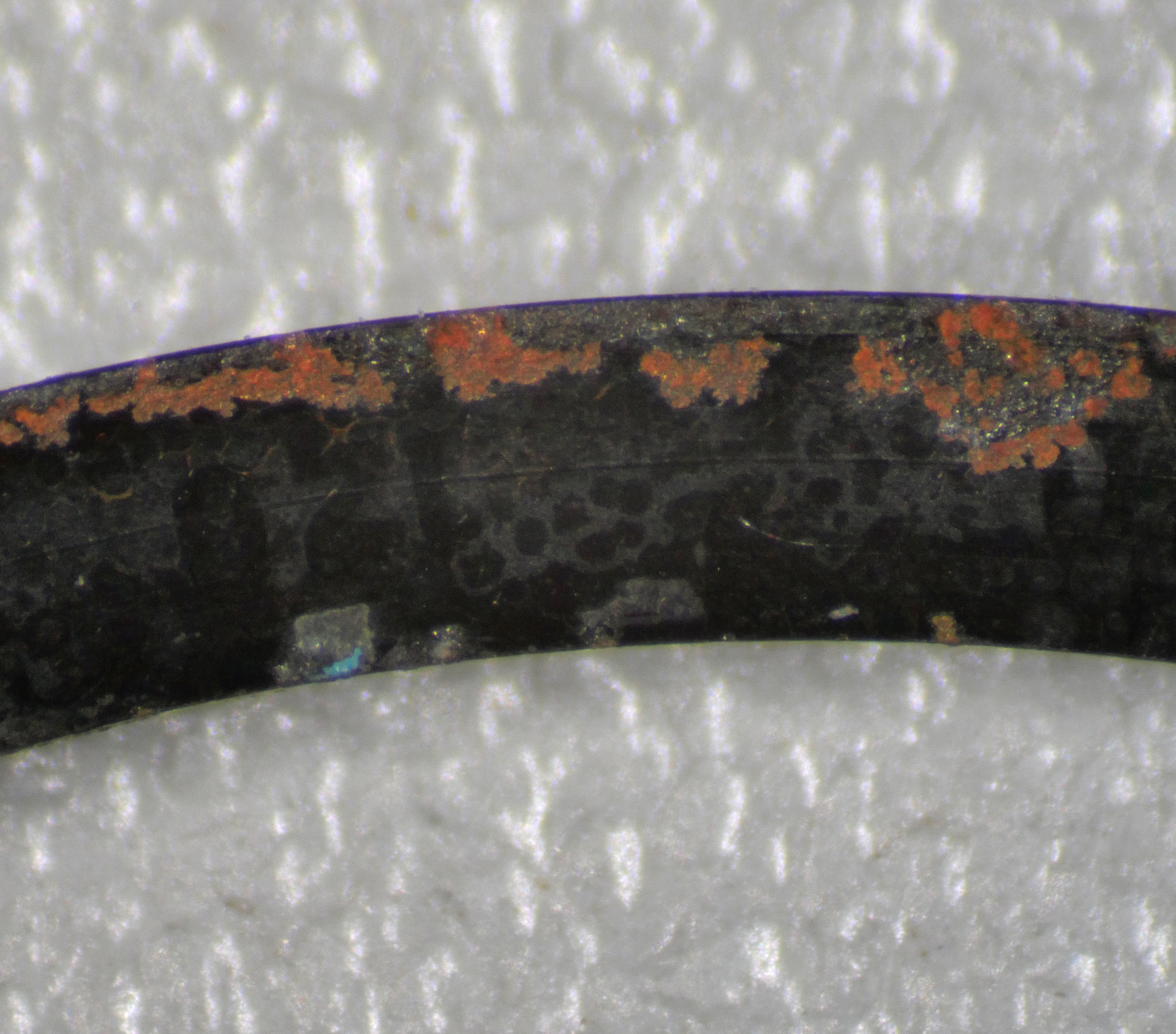
I have an idea for how to deal with that but I’ll get to that later on. Let’s turn our attention now to the two counter disks.
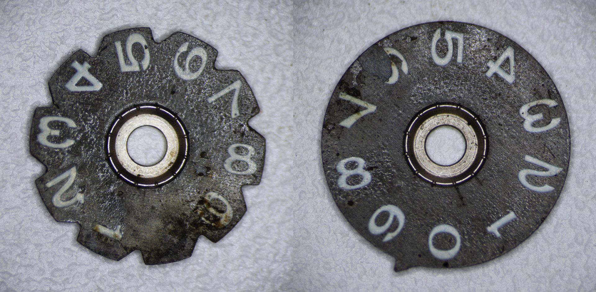
This photo, taken under the harsh overhead lighting of a stereo microscope, shows rather better than the earlier photos, the impact of the oil. What you can probably better appreciate from these images is that the lacquer or transfer film has lifted on both disks, rendering the print extremely fragile. As we saw earlier, some of the print has already been lost, having glued itself to the rear of the watch dial. The surviving print though remains extremely vulnerable to inadvertent contact where surface tension might peel fragments away. You can see an example of this in the top of the loop of the numeral 2 on the left-hand disk. The better news here though is that the print has not been liquified in the way that it had on the tachymeter ring and so there is some scope for some careful cleaning in the gaps between the numerals. The rear of both disks are relatively clean and respond well to the sort of routine cleaning that parts such as these might reasonably be subjected to.
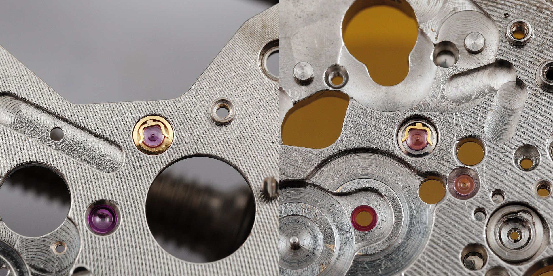
I think it’s time to lift the mood a little and begin the process of figuring out how this is all going to come back together. Let’s start squarely in our comfort zone and begin by refitting and oiling the two Diafix settings, one on the barrel and train wheel bridge and one on the main plate.
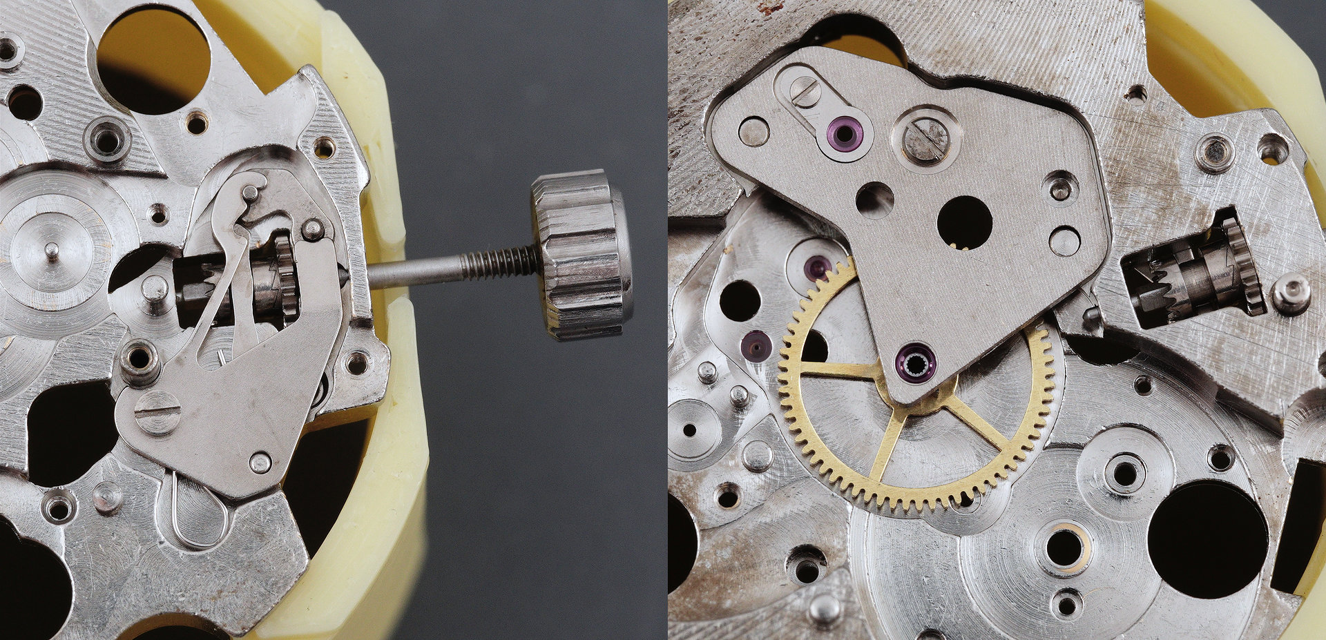
Next, we assemble the setting parts and then fit the centre wheel, its bridge and the jewelled plate to support the minute register wheel and fourth wheel pinion.
In the interests of capitalising on this initial momentum, I set about tackling the job I’ve been dreading: reassembling the minute register wheel and its delicate and fiddly tension spring.
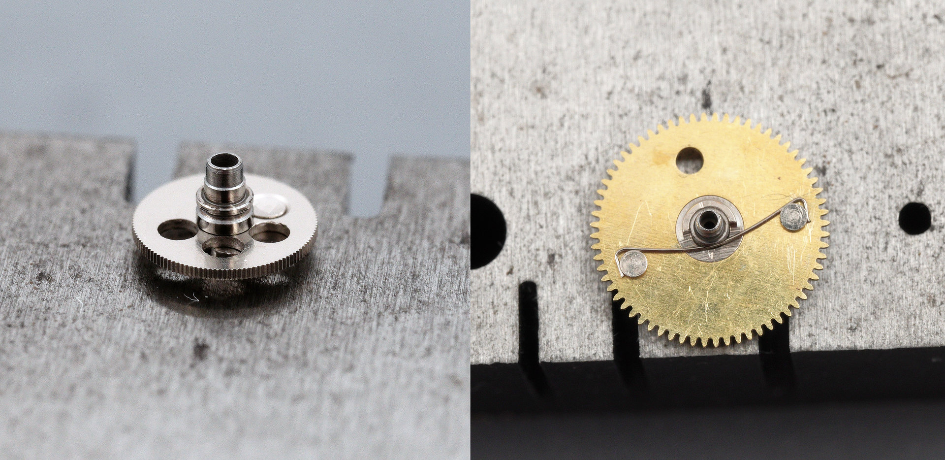
The wheel itself just sits on the pinion mounted on the rear of the braking disk, and the tension spring secures the two parts together, the centre of its bowed length sitting in a groove around the circumference of the pinion. Fitting the spring would have been a lot less stressful if I’d had a packet of spares at my elbow but I didn’t and so I had to raw dog it, to coin an expression currently en vogue (probably miss-used but it sounds right in this context).
You may recall that the calendar plate on the dial side of the movement provides the upper jewelled bearing for the third wheel and so before contemplating reassembling the gear train, we have first to construct the blizzard of complexity that provides all of the functionality on the dial side, topped off with that calendar plate. The dial-side Diashock will be buried beneath and so that’s as good a place as any to start (along with the minute wheel, its plate and of course its intermediate wheel).
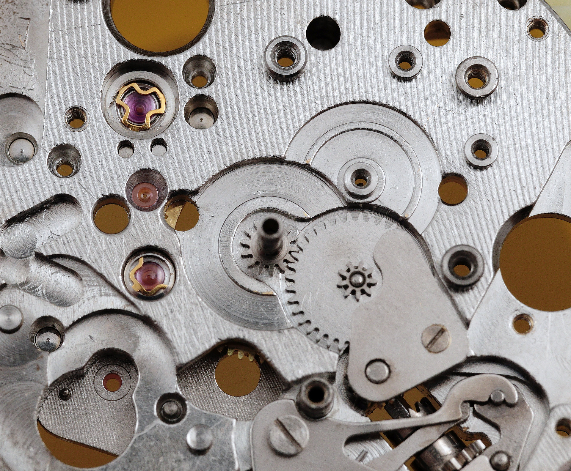
Working the process in reverse by which I have found myself in this position, I reckon the minute register hammer comes next, as it sits beneath the brake levers.
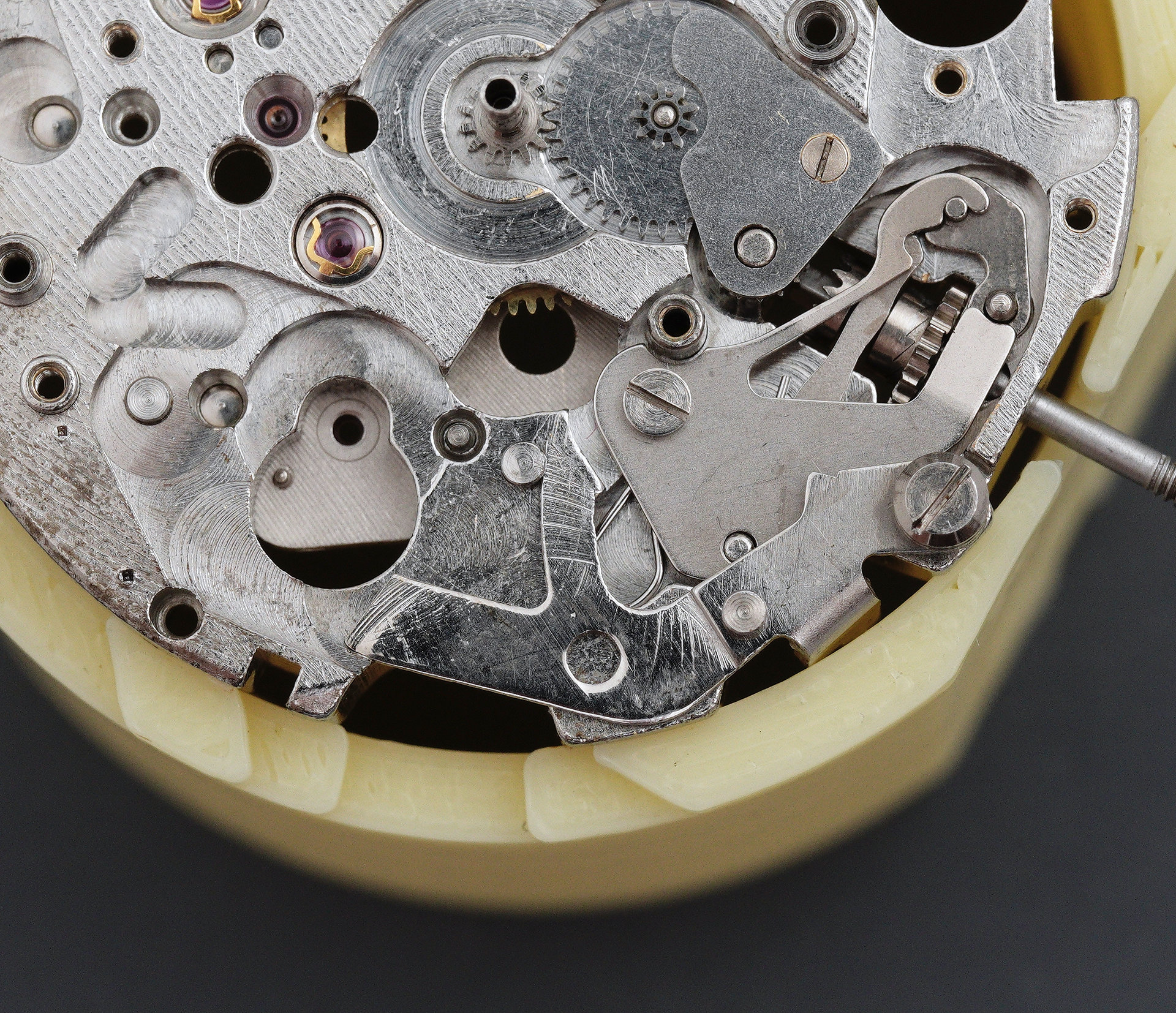
Talking of brake levers, let’s fit the minute register brake lever.
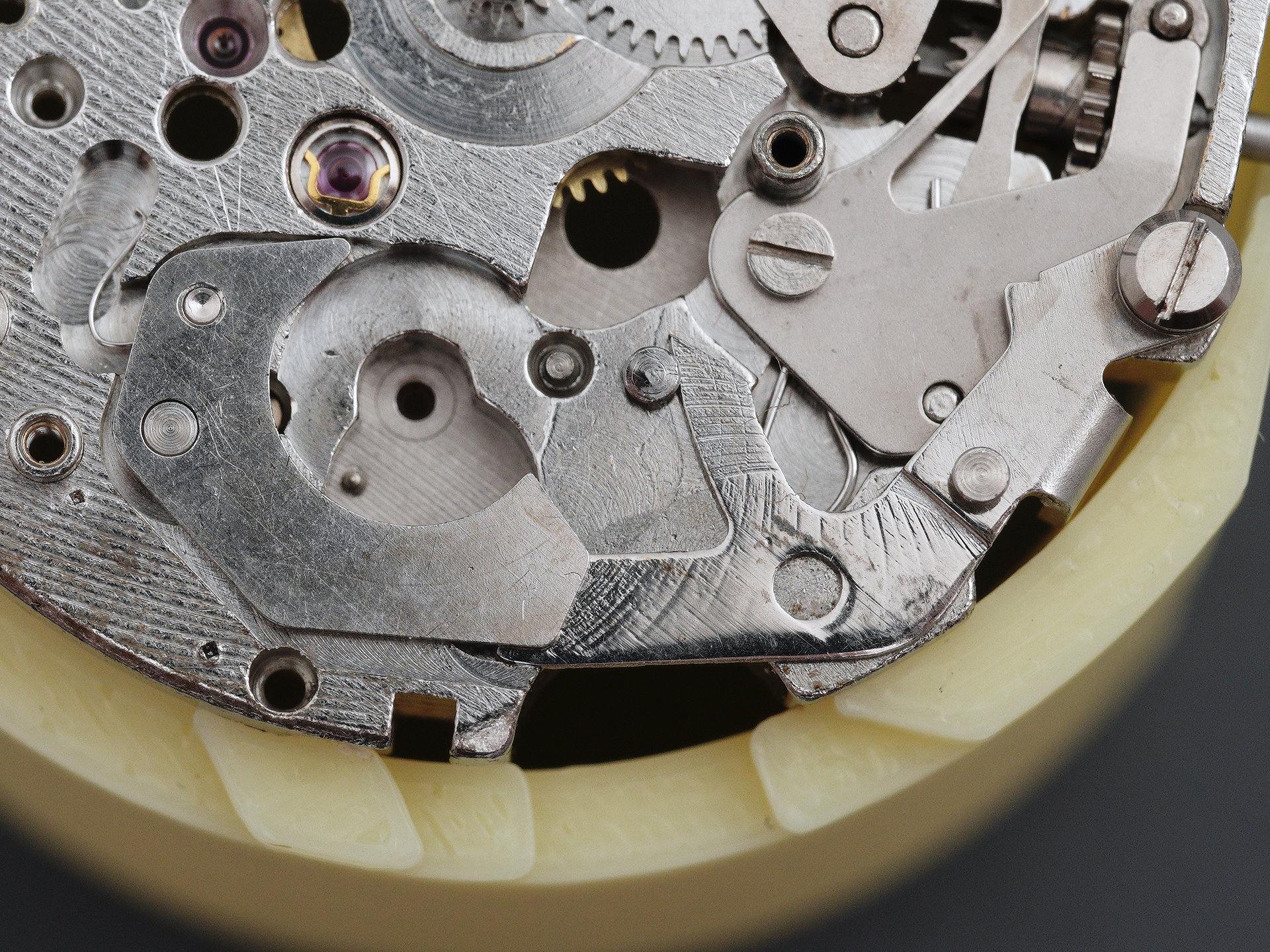
Its transmission lever finds its way into position next, secured by its left-threaded screw.

Focussing our attention on where the two interact, we can get a better idea of how they work in concert to halt or release the minute register pinion.
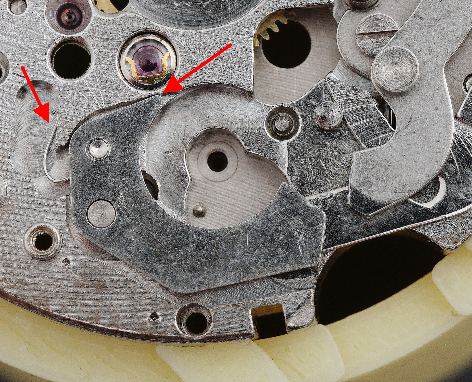
The brake lever rotates about the post adjacent to the screw hole in the lower left part of the image above and its resting state is defined by the force exerted by the hooked spring indicated to its left. That force rotates the lever anti-clockwise until the tip of the arm, uppermost (indicated) comes into contact with the wall of the cutout in the main plate. In this condition, the inner circumference of the lever is in contact with the toothed wheel on the underside of the minute register pinion, preventing it from rotating. When the chronograph is started by pushing the start/stop button, the transmission lever rotates clockwise about its pivot point and its tip comes into contact with the sloping right-hand edge of the brake lever, forcing it to rotate clockwise about its pivot, releasing its grip on the minute register wheel pinion: the pinion and wheel are then free to rotate together, driven by the third wheel pinion. The important point to appreciate is that the minute register wheel is rotating continuously as long as the watch runs and it is the central pinion that starts and stops as choreographed by the interactions between the transmission lever and the brake lever.
The next pieces of the puzzle are: first, the hour wheel, because it sits beneath; the calendar driving wheel, secured by its left-threaded screw; then the moustache-shaped jumper spring; followed by the two mirror-imaged lap counter jumpers, both secured, once again, by left-threaded screws.

The unit lap-counter transmission lever is fitted next, pivoting about a regular screw over on the left side of the main plate, guided by a second sitting north of the two jumpers. The end of the transmission lever sits beneath the corrector lever and with which it collaborates to advance the unit lap counter disk via the star mounted to its rear. The corrector lever is secured by yet another triple-slotted screw.
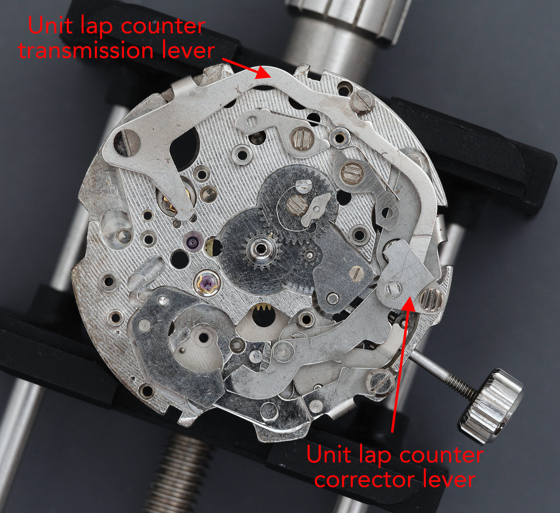
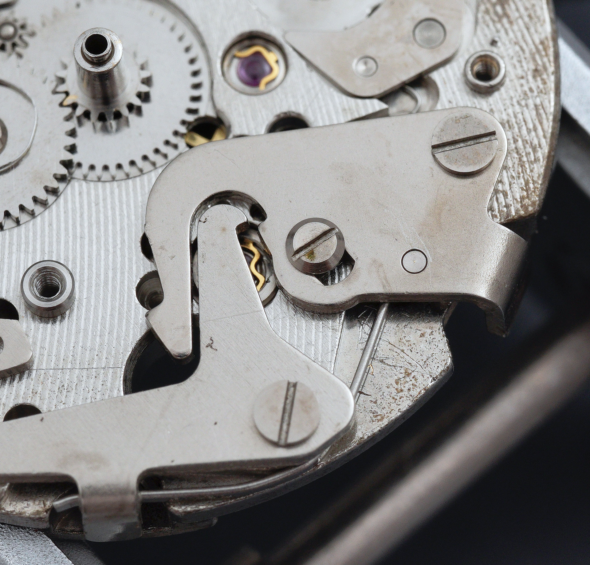
We seem to be making some headway. The 10-lap counter advance lever, being situated so much closer to its quarry than the unit-lap advance lever, comprises just a single piece. Its profile however is still somewhat complex in that it needs not only to interact with the star to the rear of the lap counter disk, when called to do so, but it also needs to collaborate with the unit-lap counter lever when it is called to action insofar as the latter locks the former in its ‘at rest’ state to avoid accidental activation of both simultaneously.
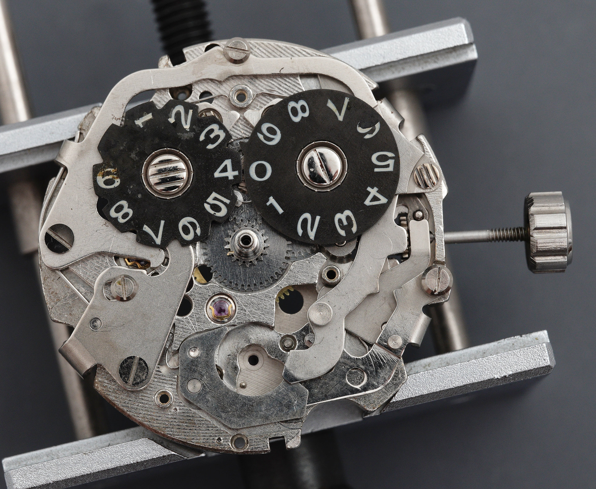
The two lap counter disks are fitted next, the left-hand disk secured by a triple-slotted screw, the right by a regular right-threaded screw. This is because the right-hand disk rotates clockwise while the left disk rotates anti-clockwise.
We are now very close to wrapping this side up. The final component to find its place before the calendar plate is fitted is, of course, the minute register wheel. We need to prepare the ground first by fitting the transmission lever spring and resetting the position of the lever so that it comes into contact with the brake lever. Thus, there is no impediment to dropping the register wheel into its cavity, the lower part of its pinion locating into the reverse side of the jewelled plate fitted to the centre wheel bridge (see earlier).

A casualty of the steps required between fitting the two disks and fitting the register wheel has been the loss of part of the lower loop of the 3 numeral on the 10-lap counter disk, due probably to the unconscious light contact from the tip of a finger-clotted finger. The operation of the entire dial-side mechanism requires the discipline imposed by the calendar plate and so we cap off this part of the adventure with that plate.
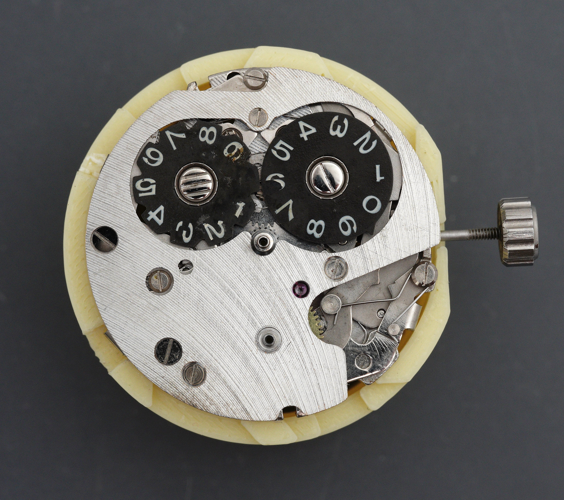
You can see more clearly here the path taken by the minute register transmission lever spring (lower right quadrant, above). With that wrapped up but not yet properly tested, it’s time to flip over to the other side and start rebuilding the gear train. As with all movements, that begins with the power source.
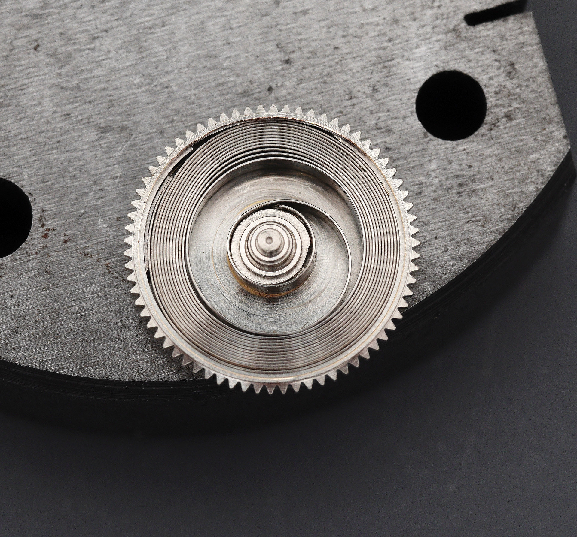
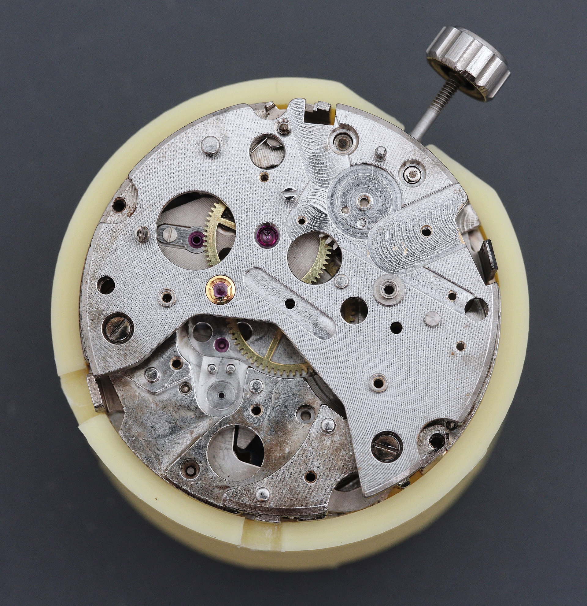
Setting the cleaned and rehoused mainspring to one side for the moment, this seemed like an opportune time to test-fit the barrel and train wheel bridge with the third wheel in place to test end shake, having replaced that jewel (you remember that jewel don’t you?).
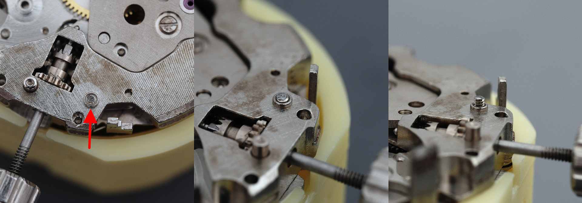
A minor adjustment completed and I noticed once again that missing train bridge screw. Easy enough to source a replacement, as it’s a part shared with other members of the family, but when I removed the bridge, I discovered that yes, the screw head was missing but unfortunately, the thread was not, still nestled inconspicuously in its hole. There was no way I was going to undo all that work on the dial side to extract the broken thread and so I started working at the remnants with an old oiler and little by little I was able to work it, work it, work it and gradually teased the little blighter out into the open. What a relief!
The reconstruction of the gear train then follows unimpeded by loose ends: clockwise from upper left, below: the barrel and ratchet wheel (don’t forget the latter!), the escape, third and double-stacked fourth wheel; then the barrel and train wheel bridge; the friction spring for the chrono wheel and the wheel itself; and finally the chronograph bridge securing both the chronograph wheel and the fourth wheel.
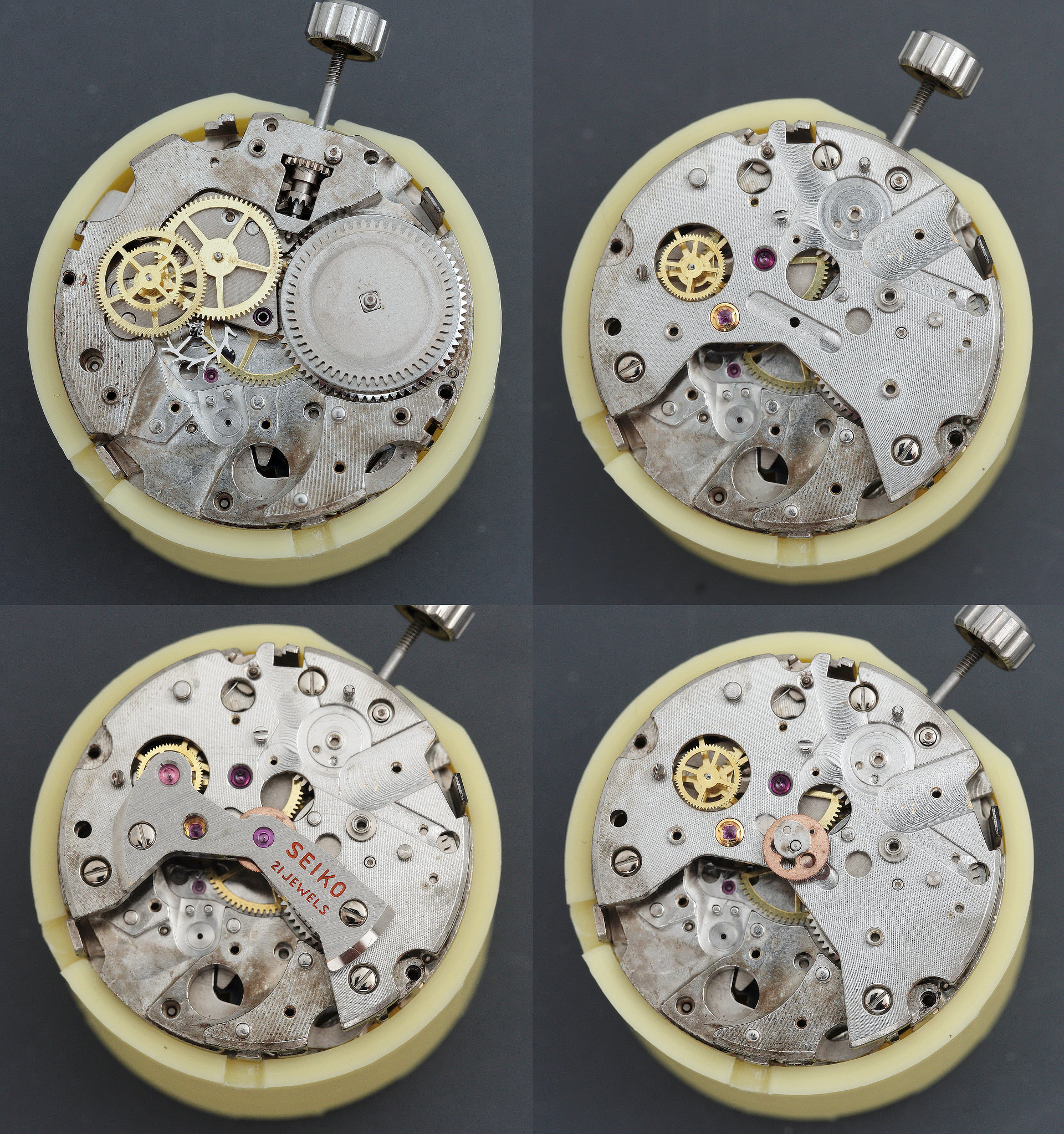
The movement is almost primed at this point to see if it actually runs, before investing time in rebuilding the chronograph mechanism. So in with the pallet fork and its bridge, lubricate the pallet stones and refit the balance, its Diashock capping things off. The hairspring was not sitting flat but adjustment to the stud position resolved that and with power to the mainspring, she was off and running.
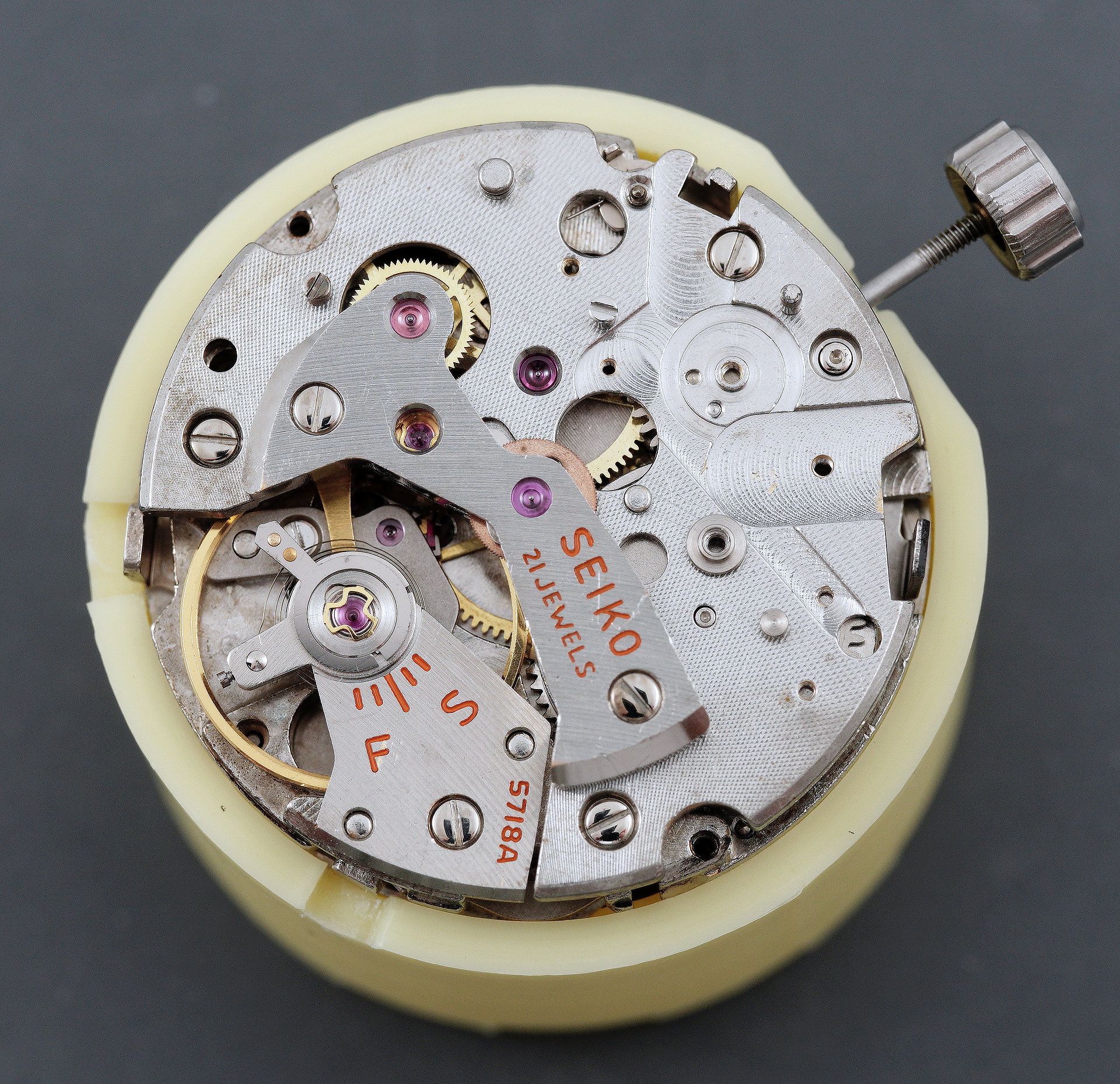
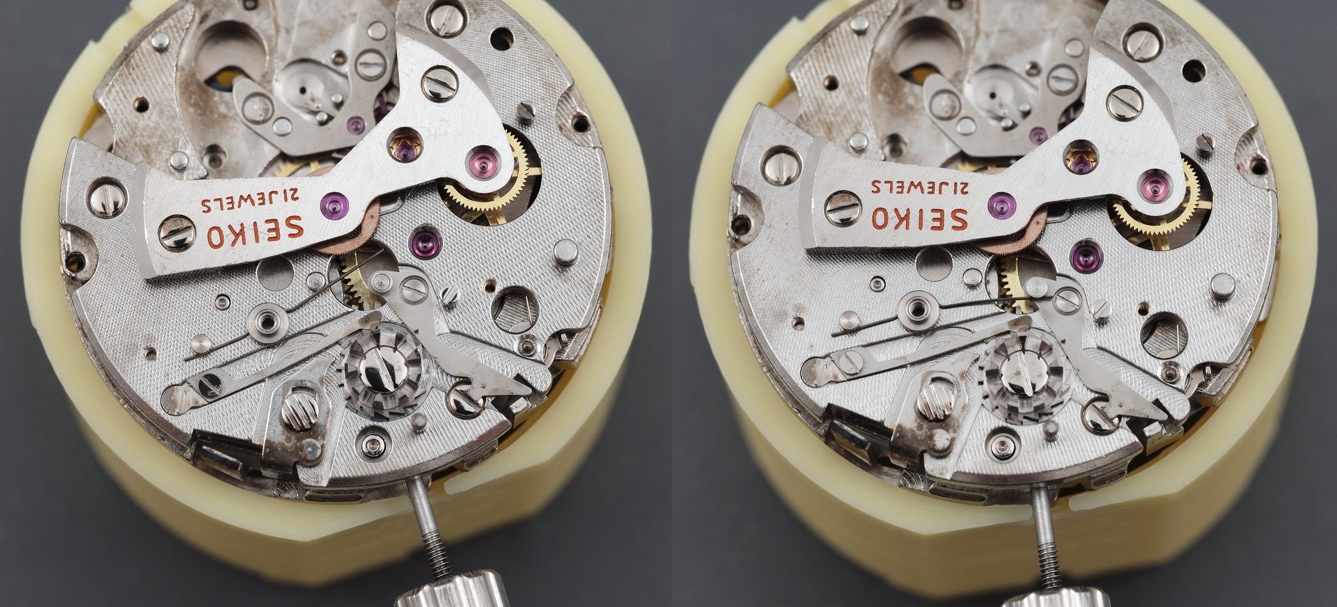
Assembling the chronograph parts feels familiar and comfortable compared with much of what has preceded up to this point, the deviations being the elements relating to the separate chronograph reset function compared to the 5719. Thus, we begin by removing the balance, for safety’s sake, and then fitting the castle wheel, its jumper, the operating lever, the reset lever spring, and the reset lever. The difference between the left- and right-hand photos below is that I’ve hooked the end of the reset lever spring beneath the post at the end of the lever in the right-hand photo.
There is nothing much to be gained in an exhaustive documentation of the rest of the chronograph mechanism work other than to pause at the point at which the brake lever has been fitted, but not yet secured …
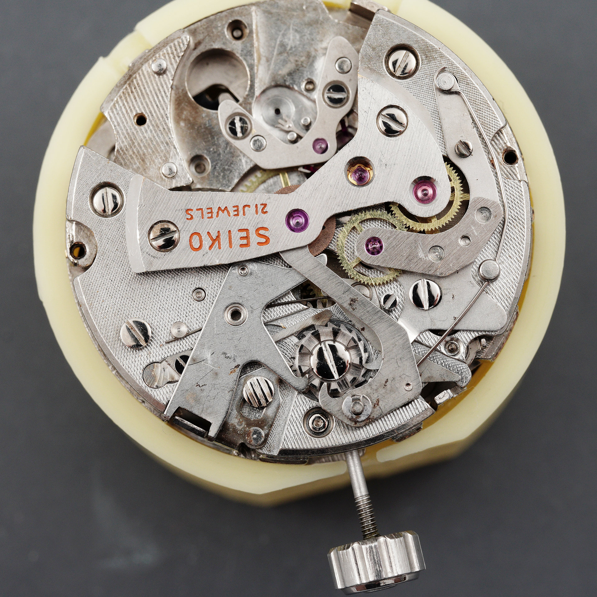
…following which we complete the deal by fitting its spring, testing the functions and then refitting the balance.
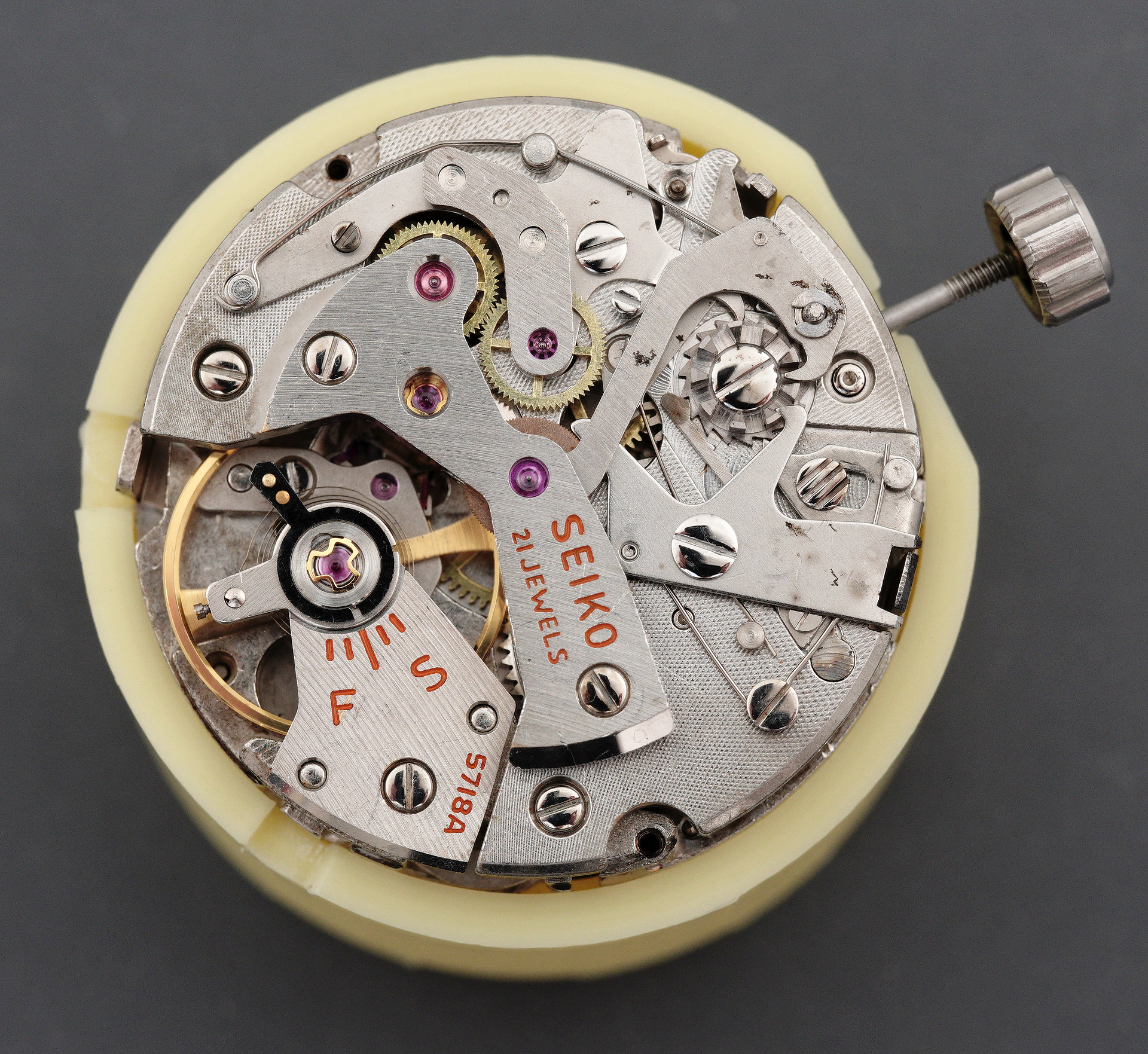
This marks the completion of the movement work, barring final testing of the operation of the dial-side functions (and replacement of the cracked c-clip with a new part). In part 4, we’ll tackle the case, chase down some movement gremlins and complete the final assembly of the watch.


Although I have a 5717 waiting for my ministrations, I’ve never seen a 5718 in real life, and to spend so much time delving into its innards is such a treat! Looking forward to the next gripping instalment as they used to say (at the end of Flash Gordon maybe? Saturday morning pics).
Thanks Pip. I am finding myself enjoying it far more in retrospect than I did at the time! One more installment on Sunday I think.