
snowflake*/ˈsnəʊfleɪk/ Noun
- a flake of snow, especially a feathery ice crystal, typically displaying sixfold symmetry
- an overly sensitive or easily offended person, or one who believes they are entitled to special treatment on account of their supposedly unique characteristics
- a white-flowered Eurasian plant related to and resembling the snowdrop, typically blooming in the summer or autumn
- a term used to describe the uniquely textured surface of a watch dial evoking freshly fallen snow, typically fitted to Grand Seiko or Seiko watches.

In 2004, following the release of the first Spring Drive-powered Grand Seiko, the SBGA001, the design team that worked on the development of that watch were tasked with the challenge of creating a dial that reflected the beauty of the Nagano mountains that surrounded the Shinshu Watch Studio in Shiojiri where Grand Seiko’s Spring Drive and 9F-powered quartz watches are made. The craftsmen and women there decided to create a dial with an uneven surface that evoked the pure white, freshly fallen snow covering the slopes of the mountains that dominated their view from the windows of their studio.

In reviewing historic samples of dials used in vintage Grand Seikos, the leader of the studio noticed a sample from 1971 which they later identified as having been fitted to an 18k yellow-gold-tonneau-cased 56GS (the 5641-5000). That dial though was not white, but golden coloured, and so having identified the texture that they wanted, they set about developing a process to produce a pure white finish that did not dull the crisp contouring of the dial surface. The method that they chose involved electroplating silver to a thickness that produced a pure white finish that satisfied their original design objective.

The resulting Spring Drive “Snowflake” was released in October 2005. The model survives to the present day in the form of the SBGA211, identical to the original but now using the post-2017 Grand Seiko branding.
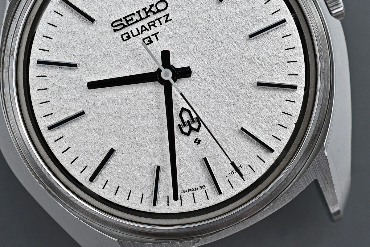
All of this preamble leads me to the following question: the SBGA011 is certainly the first Grand Seiko “Snowflake”, if you accept that the 5641-5000 is not a snowflake but, say, a “honeyflake” but is the dial fitted to the SBGA011 actually the first white snowflake dial fitted to a Seiko? I am going to suggest that it is not and that in fact the first Seiko Snowflake was the Seiko Quartz QT 38-7030 from 1973, an example of which forms the basis of this present entry.
I have owned this June 1973 watch for some time. Like many of the watches I buy, I immediately consigned it to my repository of future projects, having first ascertained that a) it appeared to be functioning and b) was in excellent condition externally, barring a rather beaten-up crystal. The case back has been inscribed upon, marking the occasion of the 50th anniversary of an electric power plant company.#

I removed the battery and left it to its own devices for a little over three years. You may have noticed from the case back that this is a unibody case and that the movement is therefore accessed from the dial side. To do so, we need first to remove the external bezel and crystal.

You may also notice at this point that the edge of the dial adjacent to the 2 minute marker is stained but that otherwise the dial appears to be in excellent condition. With the hands removed, we can take a closer look at that dial texture.

I don’t think there is any doubt that this is a snowflake dial as seemingly conceived 31 years later in the Shinshu Watch Studio in Shiojiri. The movement is released from the case by first rotating the locking case spring anti-clockwise and depressing the setting lever to permit removal of the crown and stem.

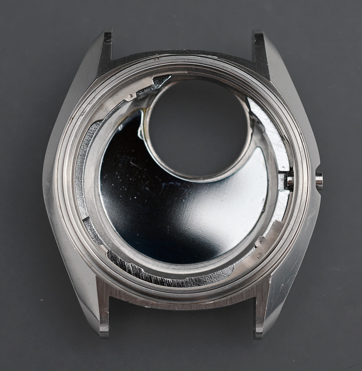
With a little jiggling the movement comes free and we can take a look at the inside of the monocoque case, complete with its anti-magnetic shield fixed to the inside rear.

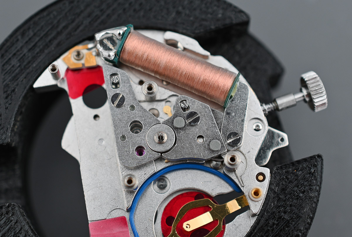
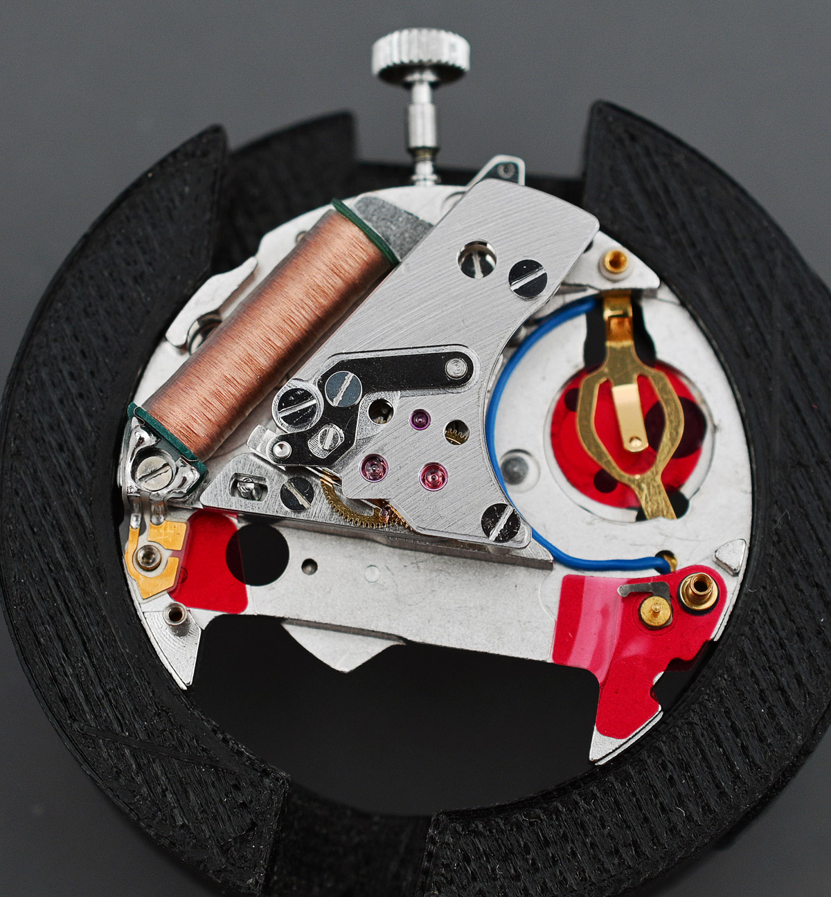
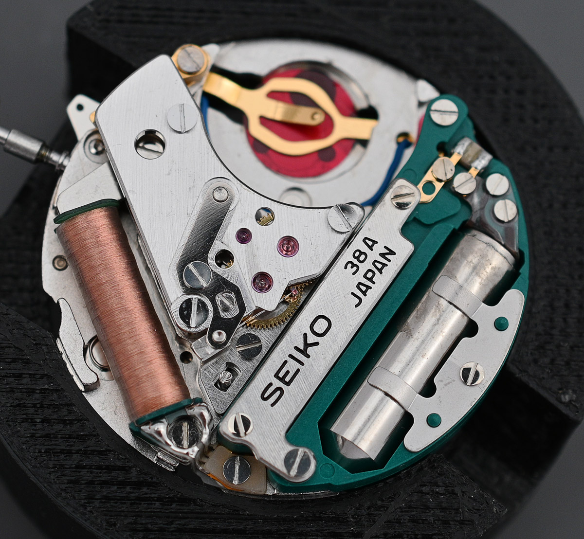
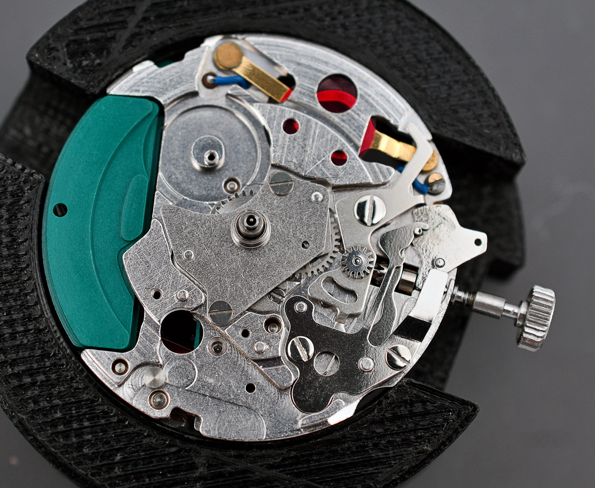
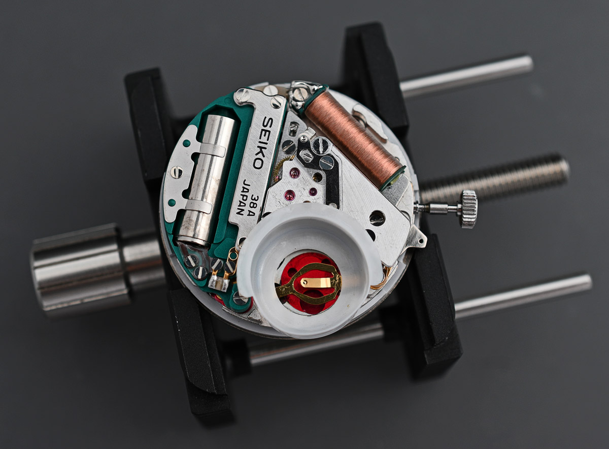
Inverting the movement and securing it onto a movement holder, we can take a look at the train-side architecture and observe, having removed the plastic battery insulator, that there are some signs of battery electrolyte leakage.

We have met this family of 16 kHz quartz movement before in the form of the 3823A movement fitted to the 3823-7001 but there are some key differences between that VFA movement (very fine adjusted) and this base model variant. The most obvious of these is that the 38A has no calendar complication where the 3823 has both day and date complications. The 3823A fitted to the VFA watch would also have been adjusted at six positions and temperatures from factory, whereas the 38A would have been essentially unadjusted.
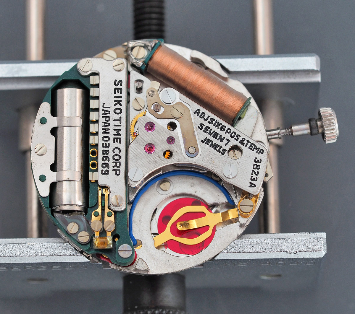
The regulation of the 3823A was made possible by the presence of step variable condensers (which the 38A lacks) as well as a condenser for temperature compensation. The 38A instead has a single replaceable condenser to allow for some oscillator regulation. The advertised accuracy of the 3823A was less than 5 s per month; for the 38A, less than 10 s per month.
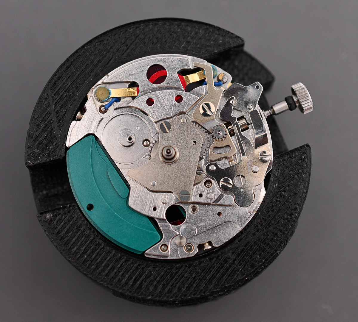
The movement deconstruction starts, as is usually the case, with the dial side and to make a start, we need first to remove that special dial. This is achieved by loosening the two screws securing the dial feet.

The complexity of the dial side of this calendar-less movement is obviously a little reduced compared with the 3823A discussed previously. The only business required of this side at this point is to remove the hour wheel which I have done already in the image below.
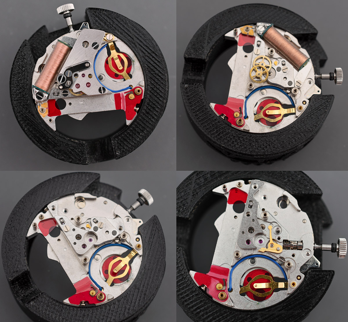
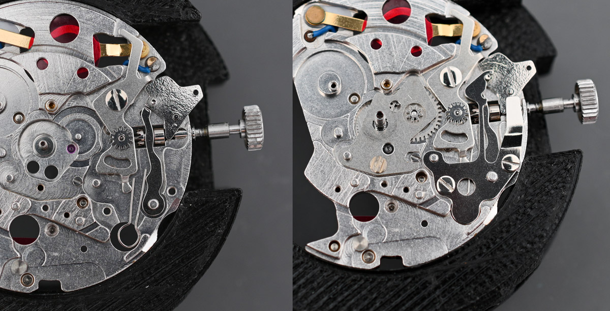
Reverting to the train side and the disassembly process proceeds smoothly. In the final of the four images shown below (bottom right), we can see the stop seconds lever that sits beneath the second of the two rotor stators.
It is worth pausing at this point to note an observation I made when working on the 3823A a couple of years ago. When I reached this point in the disassembly of that movement, I noted that the left hand rotor stator (rotor stator A) had been glued to the movement using an epoxy adhesive. I did not understand at the time why that might be the case – it seemed very unlikely that it should have been glued in the factory, and so I dismissed it as a watchmaker ‘thing’ and removed the glue prior to completing the disassembly.
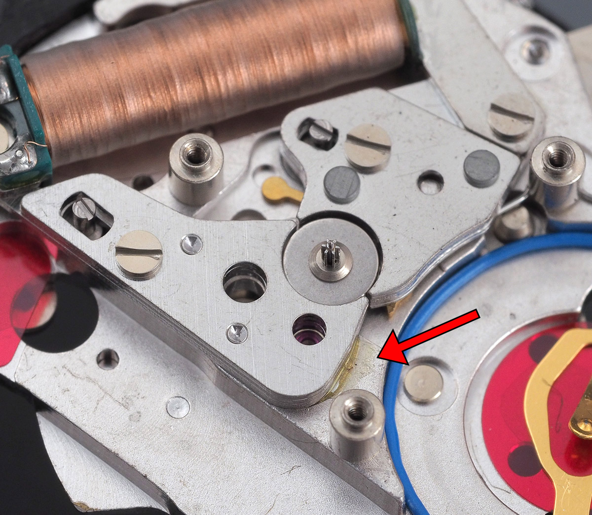
There was no such glue present in this 38A but I would ask you to store a mental note at this point, to be recovered a little later in proceedings. The remainder of the disassembly is not really worth documenting, given the detail presented in the earlier VFA post, but I will pause to note, on the dial side, the much more conspicuous evidence of fairly copious electrolyte leakage and the resulting growth of copper salts on the two terminals visible on the dial side.
In cleaning the movement main plate, I would need to consider additionally how to deal with these copper salt deposits. The main plate would not in any case find its way into the regular watch machine bath because of the plastic sheathing on the wiring and the red insulating plastic sheeting and so a combination of a vinegar/salt bath to dissolve the salts followed by a clean water rinse, then isopropanol and petroleum spirit seemed to do the trick. I manually cleaned all of the bushings and felt that the mainplate emerged at least as clean as it would have been after a tour through the cleaning machine. All of the other parts barring the electrical or magnetic parts did get the full treatment though.
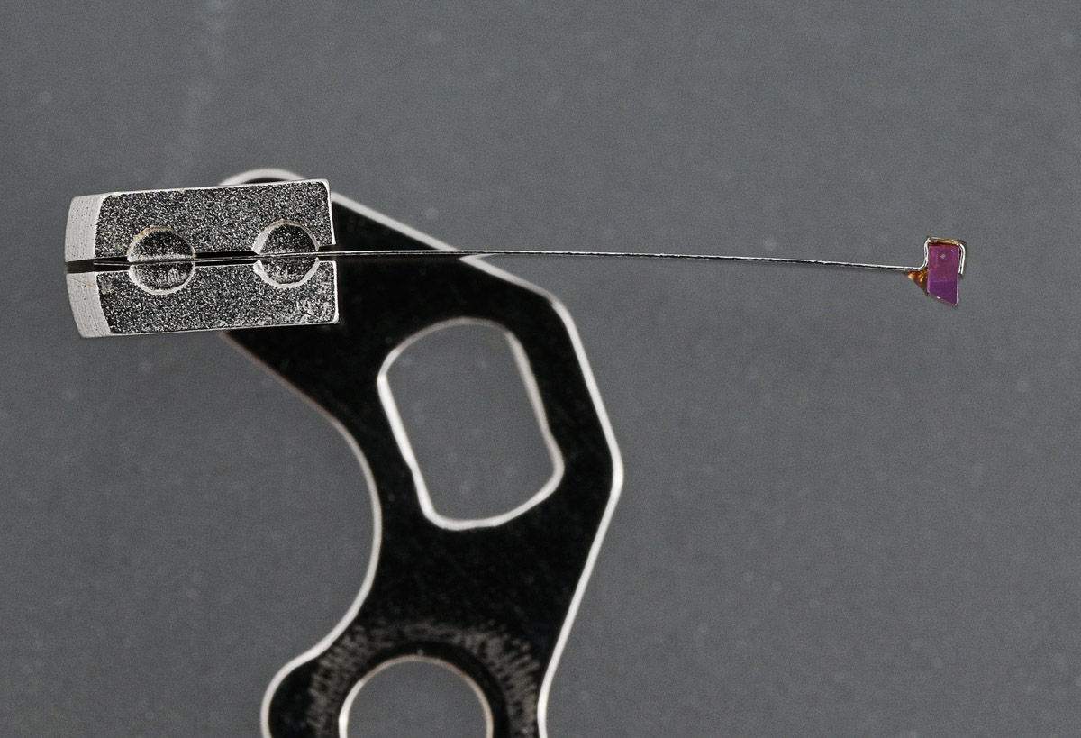
Reassembly starts with the setting parts, followed by the minute wheel, centre wheel and pinion and, most significantly, the adjustable lower end-piece for the third wheel, notable for its colourless jewelled bushing. You will note also that the bushing that serves the lower end of the step rotor is covered by the minute wheel. A decision needs to be made about whether to pre-lubricate the hole or partially disassemble later on to lubricate once the gear train is fitted. I opt for the latter.
Speaking of which, we can turn the movement over now and fit the two rotor stators followed by the step rotor itself and the coil.
The rest of the gear train follows, comprising the third wheel and centre seconds wheel, at which point we are ready to contemplate the fiddly business of refitting the bridge.

Fitting the bridge is not something to be tackled with an espresso on board nor indeed with any residual irritations with the world in general. In fact, I found that in certain states of mind, it was very difficult to get all three shafts to locate in their respective bushings and will confess here and now that my exertions appear to have resulted in the infliction of some marks to the top of the bridge from a careless use of steel tweezers during numerous attempts to get it to seat. However, using a binocular microscope made the whole procedure massively more straightforward and I was able to complete the procedure straightforwardly with no profanities escaping.
I should add that I removed the second jumper prior to attempting any of this, preferring to protect it from potential damage and to then fit once the bridge was safely installed.
You will notice that there is a gentle curve to the spring that I am not quite sure is original, but I chose to leave it like that and to adjust the strength and position using the tail and eccentric post adjusters once in position.
The battery condenser is fitted next, ensuring that it is neatly tucked beneath the bridge and does not otherwise short to anywhere it should not.
At which point, we can refit the circuit block.
At this point, I decided to give it some juice and see if the movement ran. It did not. This was most vexing. My attentions had transformed a working quartz movement into a non-working quartz movement. This is not how this is supposed to go. But it is consistent with my experience of working with this family of movements in the past insofar as my initial attempts to breathe life into the 3823A VFA movement were also met with a lack of impulse. The cause then was a maladjusted pair of rotor stators and so I wondered whether that might also be the case here too.
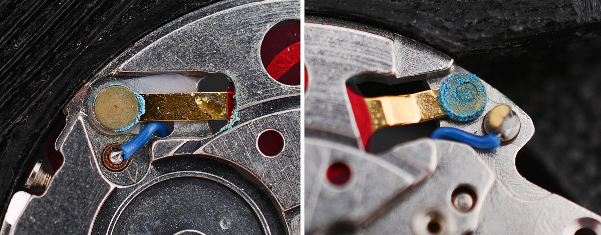
Those of you who have read the post describing the restoration of the 3823 VFA watch may recall that the technical guide for this movement suggests that the gap between the edge of the rotor and rotor stator B (gap b below) should be larger than the adjacent gap between the rotor and stator A (gap a) and that gap c should arguably be a little smaller than gap a. These gaps can be observed through one of the two viewing ports in the bridge. You should be able to appreciate from the accompanying photograph that in my movement, gap b is smaller than gap a and that gap c is larger than both.
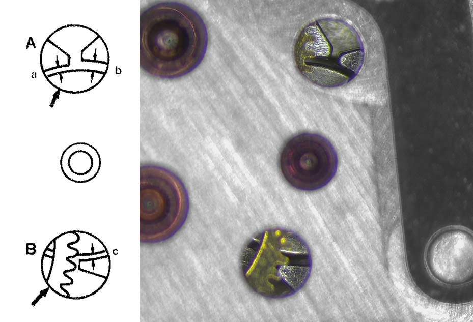
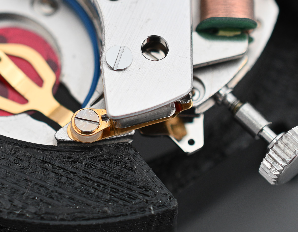
Adjusting the positions of the two rotor stators requires the bridge to be removed, the screws securing the two stators to the ends of the coil loosened and their positions then adjusted using one or other of two eccentric screws (indicated below).
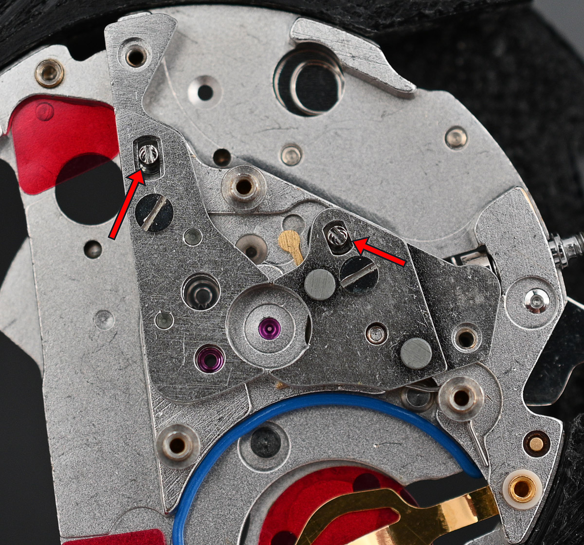
Some trial and error eventually resulted in a gapping consistent with that in the technical guide and the movement springing back into life. I would observe, however, that the critical adjustment was to stator A, the left most stator in the photo above, and significantly, the stator that had been glued into position in the 3823A, previously noted. There was method to the apparent madness of the previous watchmaker after all! Anyway, lesson learned, I can now press on. A before and after illustration of the positions of the two stators is shown in the animated gif below.

With the watch now running, I can turn my attention to the dial side and fit the hour wheel guard.
At this point, we are ready to fit the plastic dial holding ring, followed by the magnetic shield, which is clearly designed for versions of this movement fitted with a calendar.

Refitting the dial secures the shield and holding ring into position and we are getting closer to having a complete watch again.

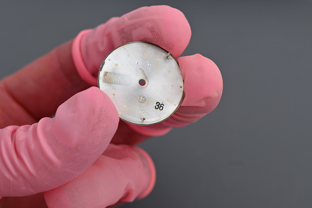
The dial, incidentally, has a date stamp that is identical to that of the case: 36 – June 1973.
The monocoque case is at this point clean and ready to receive the movement, its locking case spring rotated anticlockwise to its unlocked position.
I set the plastic battery insulator into position to the rear of the now finished movement, anticipating that it might be easier to do it this way than to try to coax it in through the battery hatch with the movement fitted.
The crown obviously needs to come out next and the movement can then be carefully lowered into the waiting case. Some general purpose jiggling was required to get it to seat happily.

Next we identify and fit a fresh gasket to the crown.
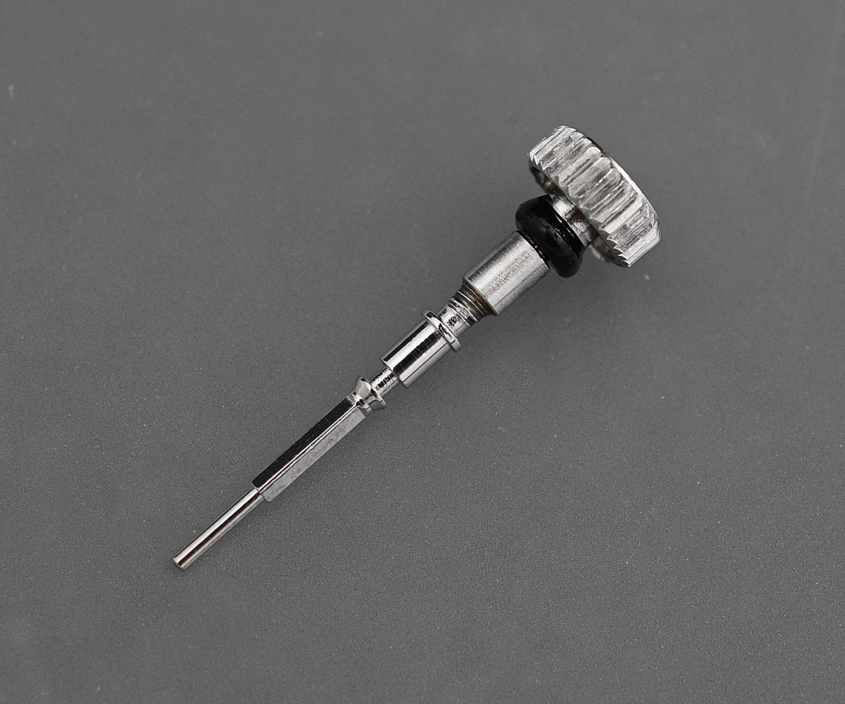
And fit the crown and stem to the movement.

I have fitted the crown and stem before moving the locking case ring back into its locked position to allow freedom of movement when threading the stem back into place. The movement is then secured by rotating the locking ring clockwise into its locked position.
Before fitting the hands, I wanted to test the function of the movement with it in situ and with a fresh battery fitted. And so, out comes the Horotec tester once more. As you can see from the photo below, the movement is running happily and doing so at +0.45 seconds per 24 hours. This equates to +13.5 seconds per calendar month which is just outside the specified range given in the technical manual.
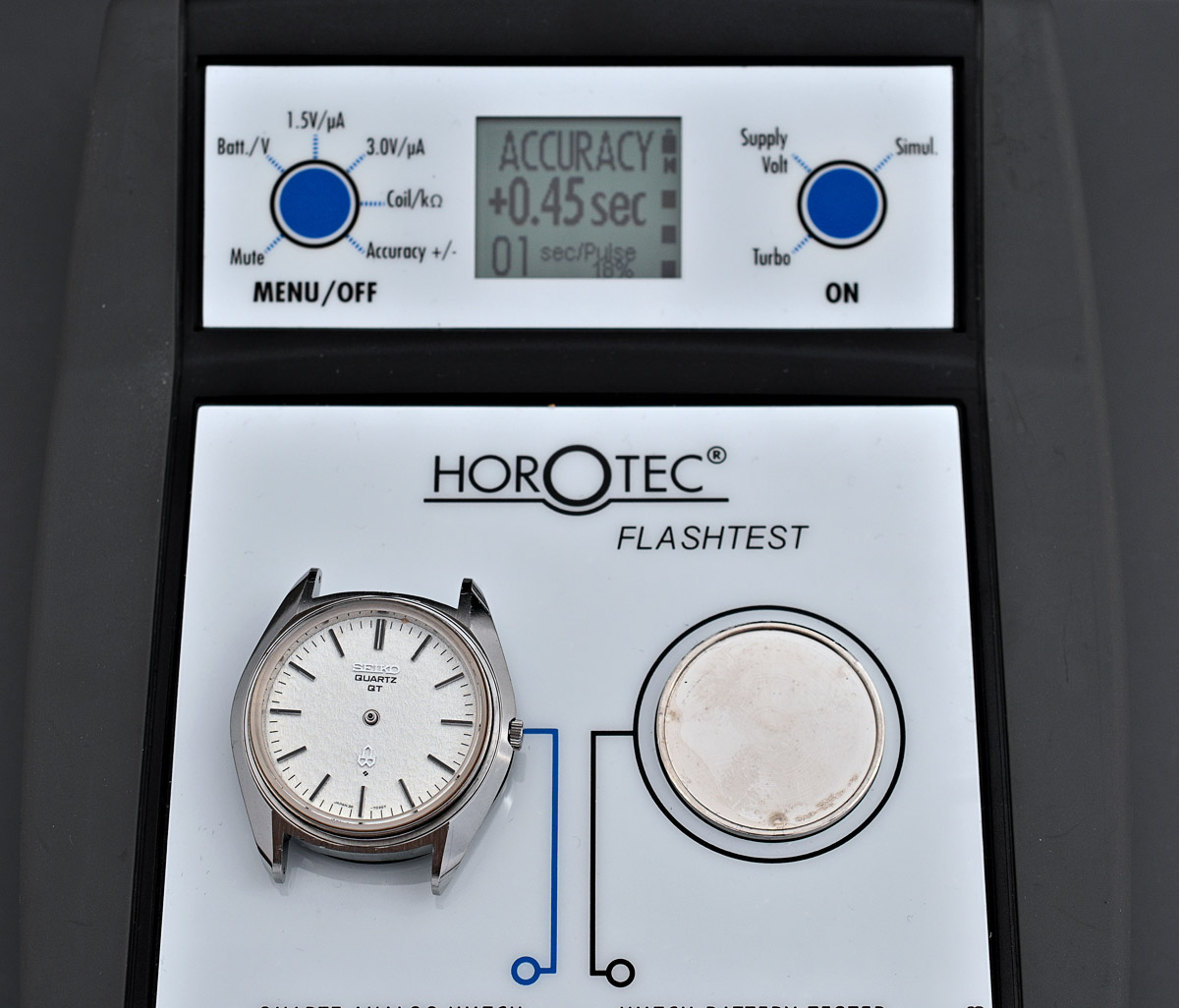
As described earlier, there is no means to regulate the movement other than to replace the trimmer condenser but I am perfectly content with this level of accuracy and so can move on to refitting the hands.

The seconds hand is aligned and fitted with the movement hacked. In the photo above, you can see that it is pausing marginally before the 7 second marker. By the time it reaches the 28 second marker it is more or less bang on and by 47 seconds it is starting to drift to just beyond each marker before settling back to just before by the time it reaches the 2 second marker once more.
Our next challenge is the crystal. The original crystal is a 300V16GNS but on this model, the crystal comes with anti-reflective coating to its underside. There is no chance at all of being able to find a new replacement with AR coating and I am not prepared to pay the asking prices for old stock 300V16GNS, especially given the likelihood/possibility, that the glue securing the crystal to the frame will have clouded. I do have an old stock 3803-7031 case complete with new crystal but this does have cloudy glue and so I reject using that crystal as a replacement. I am resolved once again to replace the crystal in the frame using the approach documented in previous posts here and here.
The first step requires the original crystal and frame to be submerged in water at about 80ºC in an ultrasonic bath and then sonicated for up to 45 minutes.
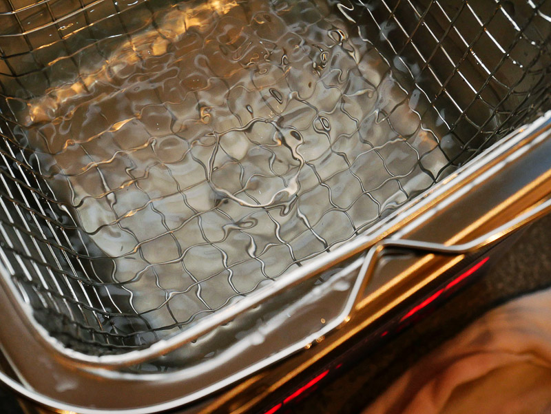
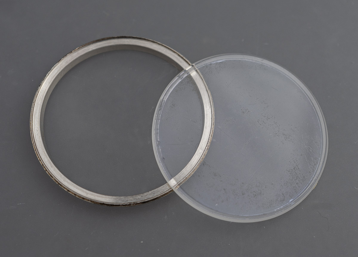
For me at least, this is the only approach that seems to work every time. As soon as the crystal is free, any remaining glue needs to be removed from the metal frame while it is still wet and warm. At this point, we have a separate frame and crystal.
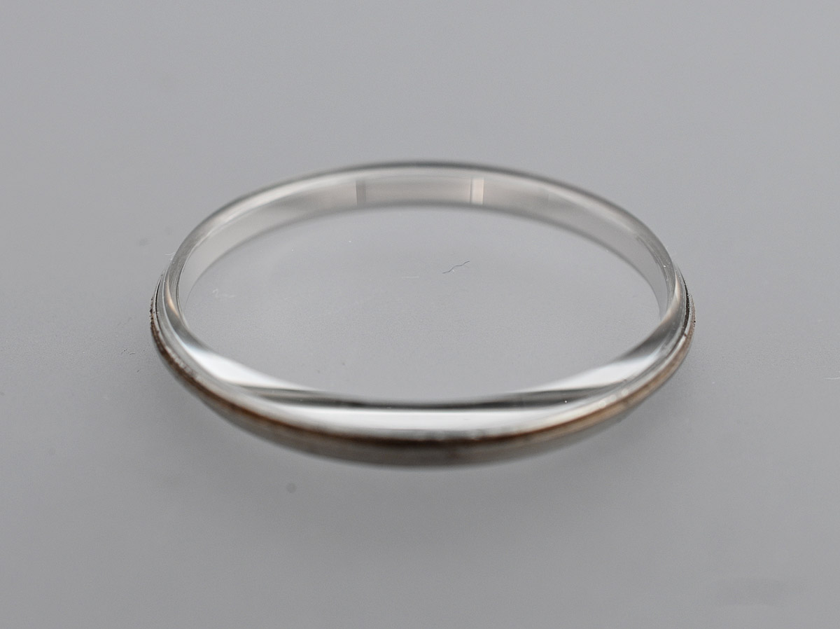
The frame is a bit tarnished around its outer edge but this will all be hidden when the bezel is refitted and so I am not sweating this one, content simply that it is clean. The next step is to select a replacement crystal. In the past, I have experimented with generic Sternkreuz crystals (see here) as well as genuine Seiko crystals salvaged from more freely-available (at the time) 30 mm diameter V-series crystals. However, about a year ago, I was approached by a watchmaker and watch crystal manufacturer based in San Francisco. He had recently duplicated a King Seiko 30mm crystal for a customer and wondered if I’d be interested in giving a sample of his crystal a try. I jumped at the chance and he sent me a couple of samples last August. Finally, I am in a position to give one of those samples a try.
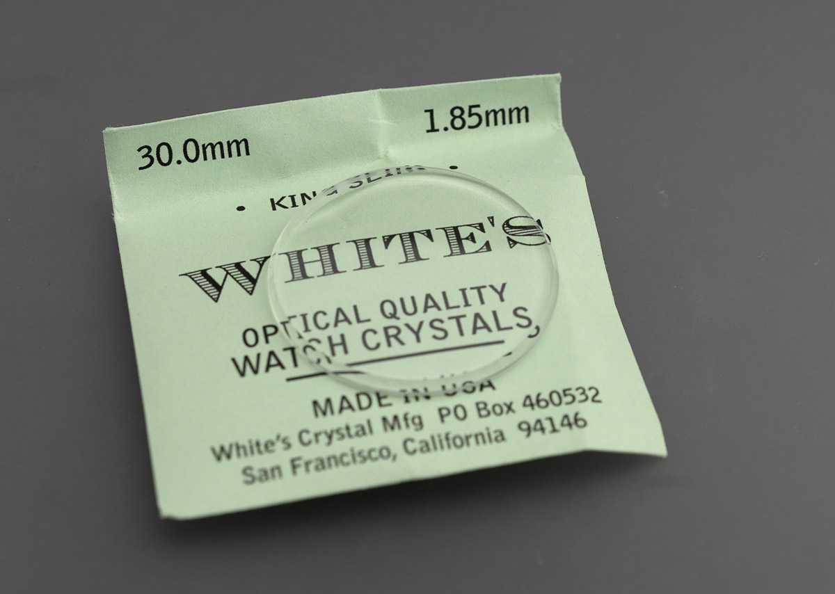
According to the maker, these are not surface hardened, but made from 1.85mm Schott borosilicate and should be very clear optically and durable. My glue of choice is Seiko’s S314 UV-curable adhesive. I deposit a thin layer of the glue around the flat mating surface of the frame, set the glass in the frame and then leave to cure for an hour or so under a UV lamp.
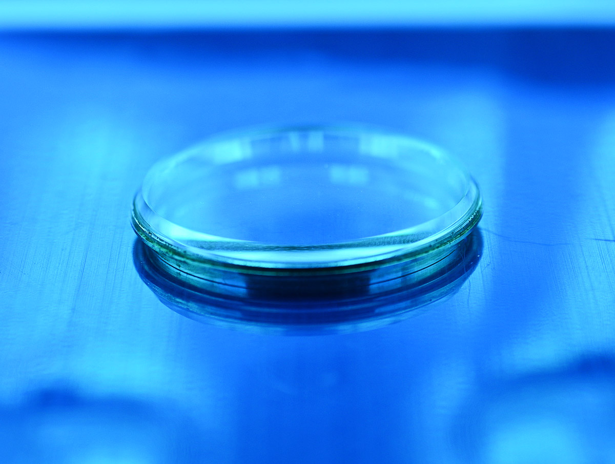
The end result looks excellent.
The crystal sits on an L-profiled rubber gasket which in turn is supported by a metal ring and it is this that next needs fitting.
The original gasket had swelled and was no longer fit for purpose and so a replacement was sourced from a spare KS case. With the gasket set, the crystal plus gasket can be placed into position and gently pressed down to help the gasket to seat properly.

We are ready to refit the bezel whose job it is to securely locate and seal the crystal to the case.
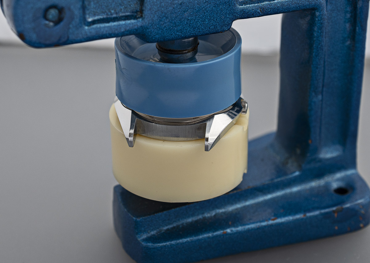
With the bezel fitted, the watch is complete and looking really rather dapper.

As with so many of the early Seiko quartz models from this era, this watch reeks of quality and top-tier engineering integrity.

But this model projects that extra something special in the beautiful mixture of linear brushing to the lugs, contrasting with the polished chamfered edges of the case and above all, that spectacular dial.

Seiko may not have had Nagano mountain ranges in mind when they conceived and executed this dial but it is, nonetheless, clearly the progenitor of the modern snowflake dial Grand Seiko.

*Three out of four of these definitions from Oxford Languages, courtesy of Google Dictionary
# Thanks to Jerome and his wife for the translation!

Hi Martin,
FYI, I asked my japanese wife… this watch was not given because of ” a long-service or retirement company gift. “… it was the 50years anniversary of the company (which seems to be electric power-plant related company)
Jerome, thank you! I’ll update the article tomorrow.
What a gorgeous watch. Those QT’s , QZ’s , etc. are all highly undervalued and overlooked.
Wonderful article, as always. However, I’ve got a 5606-7030 with a very similar “snowflake” dial dated 1968. So there are even older snowflakes out there that will never get the ancestral credit they deserve.
I did wonder if there might be earlier examples out there and that maybe this article might flush them out! Thanks for this. I shall take a look at that model. And yes, these watches are very good value at the moment. Let’s keep it that way!
The images that I’ve found of the 5606-7030 show a textured dial but I wouldn’t say it is the same as the snowflake. I’d be interested in seeing photos of your watch.
As always Martin, I really enjoyed your write-up on the snowflake quartz. Thanks again.. Sabari
Thank you Sabari. I am really pleased to hear that. All the best Martin
Well done on bringing this one back.
Unless you’ve re-purchased a fresh bottle, it seems the genuine Seiko UV glue has a longer shelf life than the far cheaper ‘super glue’ UV product, which has a 12 month shelf life (from manufacture) before it will no longer set upon UV exposure.
I tested it before using it as it is past its use-by-date and it still sets and cures under UV. So for the moment, I’ll continue to use the same tube.
Hi Martin, I enjoy your blog and especially this entry as I have an example of this watch. My battery hatch has similar scars to yours and is really stuck despite fashioning a small pronged tool to try to open it. I have changed the battery through the crystal this time, but do you have any tips for loosening the hatch whilst the movement is out?
Hi Simon, I have had one experience previously of a jammed bayonet-fit battery hatch that was the result of a previous installation 180 degrees out of correct alignment. I was only able to release that one by filing back one of the bayonet tabs from the inside and then replacing the hatch itself from one harvested from a spare case. In this case it is a threaded hatch and assuming it’s not rusted, should respond to some determined application if torque. I have a heavy duty case back opener for such tasks but I’m not sure how well it work work on an off-centre hatch. Other suggestions: penetrating fluid? Ultrasonic bath to loosen it up? Not much useful advice there I’m afraid. Good luck!
thanks Martin, your advice worked! Ultrasonic bath 60 degrees for half an hour, a jig to hold the watch case and mounting the pronged tool in a piece of wood for extra purchase encouraged the hatch to unscrew without any new slips or gouges.
Well that’s great! Glad to have been on some help.
Very interesting. I wonder who the “Shigenobu Shibukawa” that quartz watch was originally presented to was.
Thanks for showing reviving of this watch. This post inspired me to look for a 38-7030 of my own. I found one that the seller on Yahoo Japan (I use Buyee) listed as untested. It looked good so I won the auction. It worked with a new battery. Like yours it has a dedication in Japanese on the back of the watch (I hesitate to say case back as it is a mono case). Mine is from 1975 so perhaps companies bought this watch to give as award watches?
Hey Martin, very cool. Just procured a gold cap version. Will have to perform some of the same crystal magic…a little worried but iI have newfound confidence! Thanks as always.
Good luck! I hope it all goes smoothly.
Hey, I have a question. This watch looks so cool I decided to get one but the crystal needs to be replaced. Do you think it can be done by amateur or should I hand it over to professional ? I got basic knowledge about watches. Cheers
The tricky part of the operation is to avoid any visible glue residue. That is much easier said than done. It is important to use UV curing glue that dries completely clear. It is possible to do this as a novice but you may need an ultrasonic bath to help with the crystal removal stage and a UV lamp to cure the glue. Whether a professional will do a good job depends on the professional!
Thank you for your response. Already got my hands on it, but I’ve never opened the watch from dial side. Any tips how to remove external bezel and crystal from step 1? Should I just lever it ?
You should see a cutout at the 12 or 6 position into which you can fit a watchmakers knife. Up and down leverage should ease the bezel upwards. If you twist the knife there is greater risk of leaving marks on the case but sometimes that feels like the more effective way of getting traction. Use a Japan-style knife where the blade is aligned with the handle rather than perpendicular.
Thank you, last question. I’d like to order the same exact glass. Which ground diameter height did you use cause there is 0.5 0.7 0.9 1.2 or 1.5 mm to choose from ?
I received these crystals as samples to try and wasn’t aware that he was offering variations in ground diameter height. I just used the crystal as supplied.
Hi Martin. Thank you for your fascinating and always entertaining blog. Because of this post specifically, you got me collecting vintage Seiko watches. I have a few 38-7030s now, a Lord Marvel, Crown Special and some others. I am a technical person, but have been relying on a watchmaker to service everything for me. I am looking to start servicing myself and building out a set of tools (just picked up a NOS S-14 tool among others). Is that only for acrylic crystals or can I use that to open the 38-7030s. If not, what tool do you recommend?
Thanks! Mo
Hi Mo,
The S-14 tool is for acrylic crystals only and so is not suitable for the tempered glass crystal used in the 38-7030. That crystal is a V-series in which the glass is glued into a metal frame. You need to remove the outer metal bezel first and then lever the frame away from the case (carefully!).
I hope that helps
All the best
Martin
Hi Martin, thanks so much for this write up. I’ve just got hold of a 3803-7031 with Gold Cap case finish and will use this as a reference. One part I am missing unfortunately is the movement retaining ring. I don’t suppose that you know what the part number is for that? Thanks again, Steve.
Hi Stephen,
I don’t have the specific part number for this watch but I you should be looking for ‘snap ring’ with part number beginning 8332. For example, this part for the 3803-7040 is 83329881. That could well be the same part as for the 7030 but I don’t know. A bit more detective work may find the answer. Good luck!
Hi Martin, Thanks for your help. I think it might be 83209881 based on my investigations (Jules Borel database 3823-7010 snap ring). Still can’t source it though. I will keep searching. Steve.
Hi guys,
Because of Martin’s excellent website (thanks a bunch lol), I went down a rabbit hole of vintage Seikos. Included in this was a few snowflakes. I have one which has no impulse and the dial is wrecked, so it’s a parts watch.
Would the ring you need be in there?
Hi Mo, I am pretty sure it would be. It looks a bit like a circlip. I am pretty sure Martin shows that in one of the photos on his blog.
Hi Martin, long shot on an old post, but I’ve experienced the same swelling of the L shaped gasket when cleaning a 3802-7030, do you happen to remember a part number for the replacement you used?
thanks in advance and thanks for all the information you share.
Hi Mat,
Many of the watches of this era that used 30 mm V-type crystals used the same L-shaped gasket whose part number is EC2818B. I pinched the substitute that I used from a spare 5626-7000 case and that worked a treat.
I hope that helped
All the best
Martin
The caseback seems to be stain less steel, but is this case solid SS or something else with some kind of planting?
The case is unibody – a single piece – all stainless steel. The caseback has an anti-magnetic plate applied to its inner surface which may be what is making you think it’s not solid.
Thanks for answering up so quickly!
I absolutely see that it is used as a unibody, however looking at the photos it did look like the middle case and caseback are two pieces joined together (obviously quite permanently) and also besides from the shield plate seemed to have a “platey” shine to some parts, which led me to suspect some kind of plating. Thanks again for confirming a fully stainless structure!