
Tags
Imagine for a moment that you are a marketing executive working for a long-established Swiss watch company in the late 1950’s. Your company elves have been beavering away and have developed, in response to some inspirational top-down management directives, a new watch movement whose list of innovations has the potential to launch a new product line into the limelight of acclaim and commercial success. In your creation of the accompanying marketing materials, your remit is to strike a balance between promotion of technical innovation to excite the inner geek in your target market audience but laced with enough fluff to appeal those attracted more broadly by the lure of the latest, biggest and best new thing. The company is Girard-Perregaux and the watch is the 39 jewel Gyromatic launched in 1957.

Most Swiss watchmakers of the time would build their watches around bought-in ébauches (base movements) from specialist movement suppliers and then modify, finish and assemble to their own requirements. Girard-Perregaux was no exception and sourced their base movements for the most part from A. Schild, Peseux and ETA. The Gyromatic branding had appeared on earlier full-rotor automatic watches based on the automatic ETA 1256 but is more authentically associated with GP’s own ‘world’s most advanced automatic watch’ based on an ébauche from Peseux.

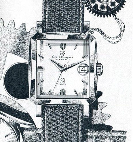
The arrival of these watches was heralded by proclamations of a double-whammy of innovation and advancement over what had come before: the headline in the advertisement shown above announces ‘The first 39 jewel self-winding watch in history …’ whilst other advertising copy describes ‘a revolutionary winding-system’ and ‘The crowning achievement of Girard Perregaux’s 168 years of fine watchmaking’. Let’s deconstruct the first of those statements: GP could have chosen any jewel count that had not already featured in an automatic watch made up to that point and it would have been ‘the first …’ and so 39 jewels is in a sense arbitrary. However, at the time, an arms race of sorts was developing among watchmakers to produce watches with as high a jewel count as possible, feeding upon the establishing perception of the time that the greater the number of jewels, the greater the quality of the movement. There is of course an essential truth in this association but only to the extent that those jewels carry some tangible function in improving the time-keeping qualities of the movement. If we adopt the more cynical viewpoint for the moment, then the choice of 39 jewels may have been a compromise between a number large enough to retain a sense that the jewel count was not being inflated purely for marketing value but not so large, in venturing into the 40s, to lose all credibility.
It is at this point that we confront that chicken and egg question: was the approach taken in designing the automatic winding module dictated by a (cynical) requirement to inflate the jewel count or was it design-led engineering that resulted in a happy accident in significantly bumping the jewel count. From a functional perspective, we really need to take a closer look at where those additional jewels are used and in doing so, we need to consider the nuts and bolts of the ‘revolutionary winding-system’.

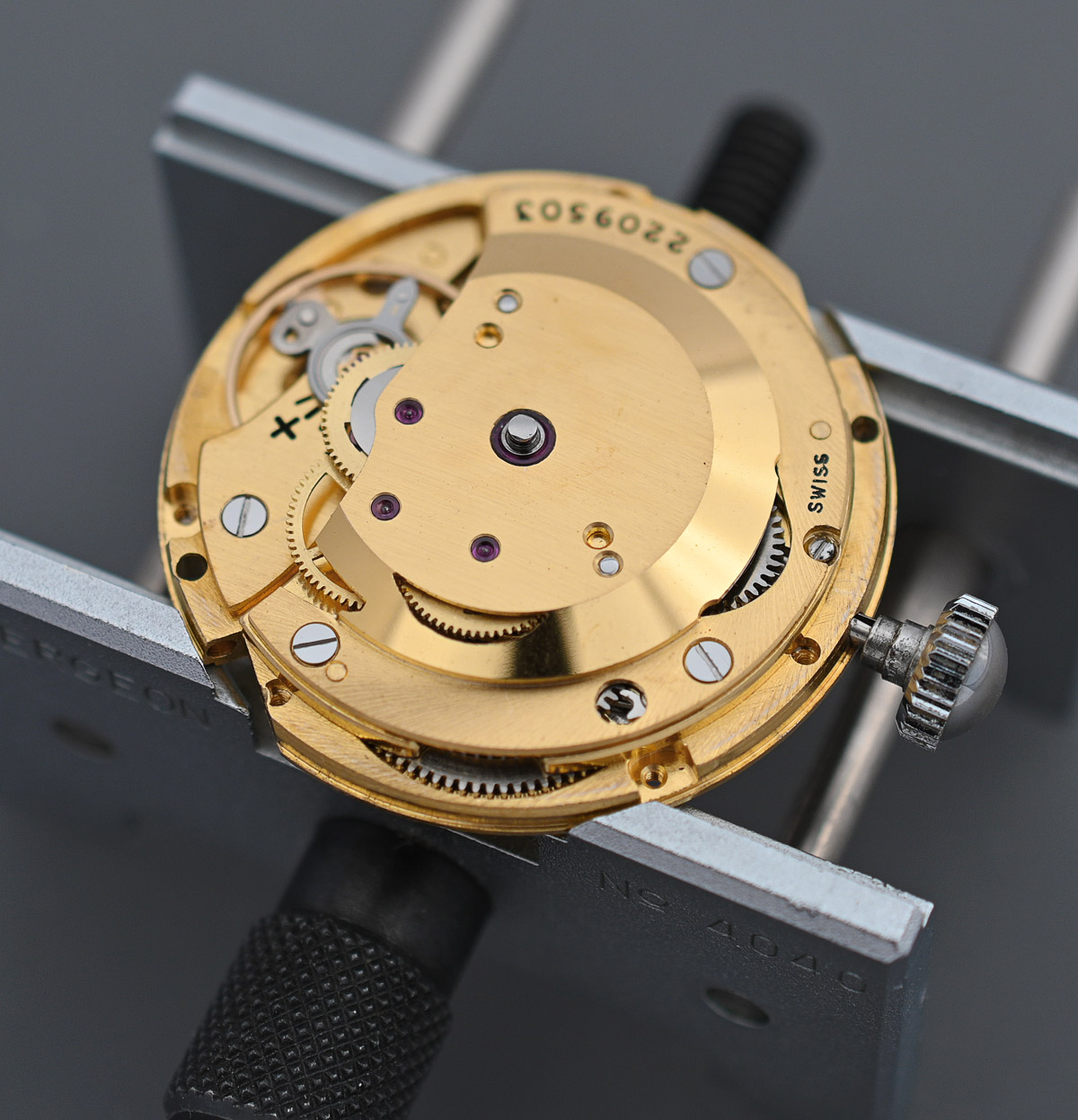
The movement fitted to these watches was either the Girard-Perregaux 21 (no calendar) or 22 (date complication) centre seconds, 11.5 ligne, 18,000 bph, full rotor automatic. The base ébauche was the 17-jewel hand wind Peseux 335 and the transformation to automatic was accomplished by the design of a separate automatic module that could be fitted to the suitably adapted base movement.
The design that GP conceived for the automatic module used a pair of reversers driven by a pinion located at the centre of a weighted rotor. The role of the reversers was to transfer the rotational motion of the rotor to a winding wheel which in turn winds the mainspring via its central pinion.
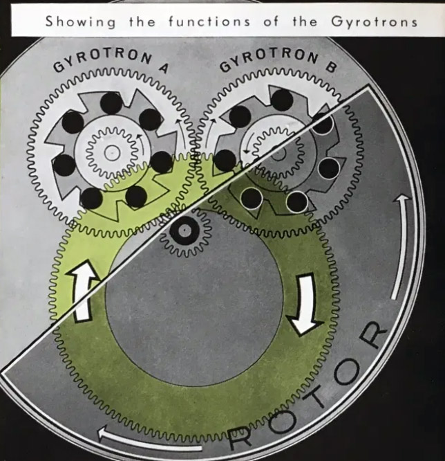
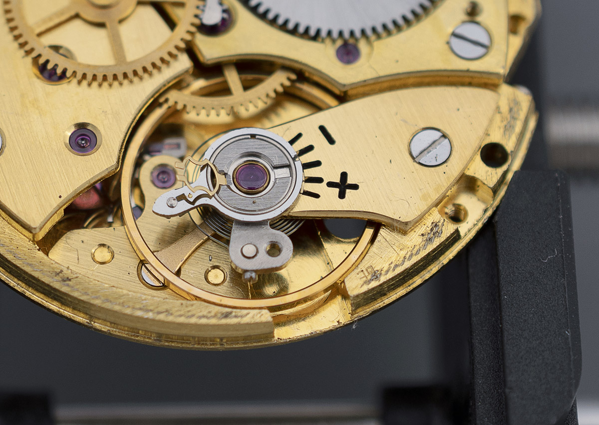
GP called the two reversing wheels Gyrotrons. There are two of them because the mechanism is bi-directional, one Gyrotron converting clockwise motion of the rotor and the other, anticlockwise. The key part of the design lies in how those two Gyrotrons perform that function: each Gyroton is fitted with seven jewel rollers, polished circular disks of synthetic ruby, whose job it is EITHER to transfer power from the rotation of the outer toothed wheel (the crown of the Gyrotron to use GP’s term) to its independent central pinion OR to allow the outer wheel to freewheel independent of its pinion. The two Gyrotrons are connected through the teeth of their outer wheels (crowns) and so their directions of rotation are opposed. As we see from the figure below, when Gyrotron A rotates anticlockwise, the 7 jewel rollers move into the narrow end of their compartments where they are pinched against the hub disk which then turns in the same direction as the outer crown. The pinion fixed to the hub disk turns the winding wheel which in turn winds the mainspring.
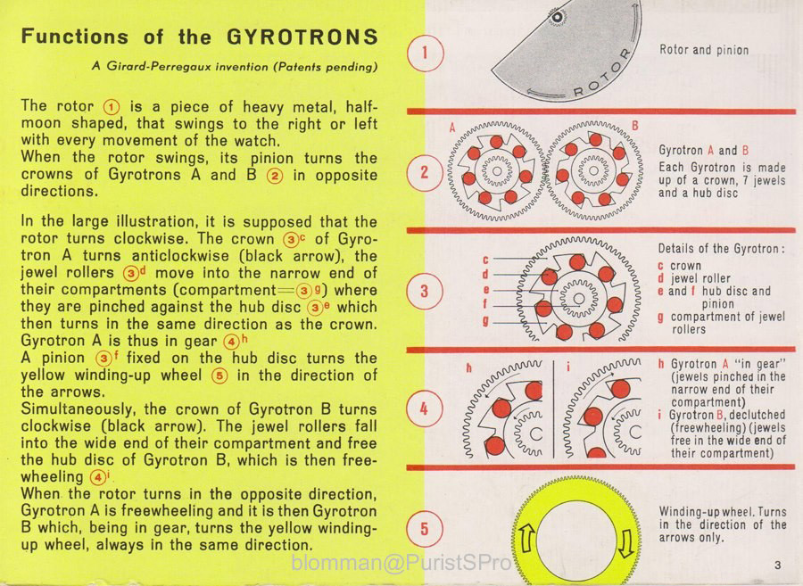
The opposing Gyrotron B meanwhile is rotating clockwise and its jewel rollers move into the open parts of their compartment, decoupling the outer crown from the inner hub disk, and the Gyrotron freewheels. The role of the two Gyrotrons is reversed when the rotor rotates in the opposite direction, with Gyrotron B then transferring power to the mainspring and Gyrotron A freewheeling. It is a very clever and neat design and one which at least to my eyes appears to use those roller jewels authentically to achieve the engineering objective. Their role is absolutely central to the function of the module. Those 14 jewel rollers of course contribute to the jewel count, with a further 7 jewels in the autowinding module serving the bearings that support the rotor pinion, the two Gyrotrons and the winding wheel and an eighth located in the barrel bridge to support the other end of the winding wheel pinion. 17 jewels in the base movement plus 1 additional jewel for the winding wheel pinion plus 21 jewels in the autowinding module equals 39. The functional jewel count that directly serves the operation of the base movement, however, remains at just 17.
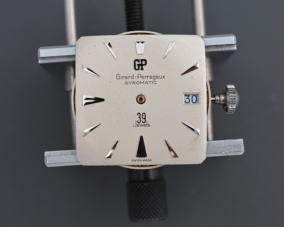
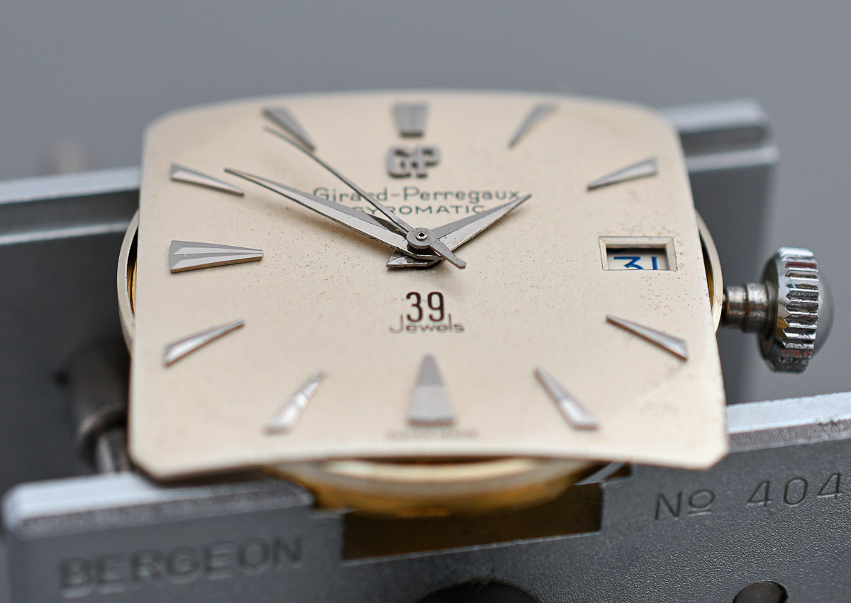
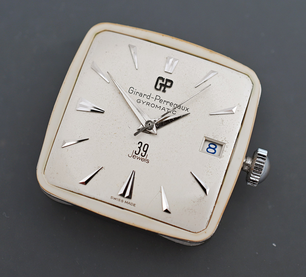
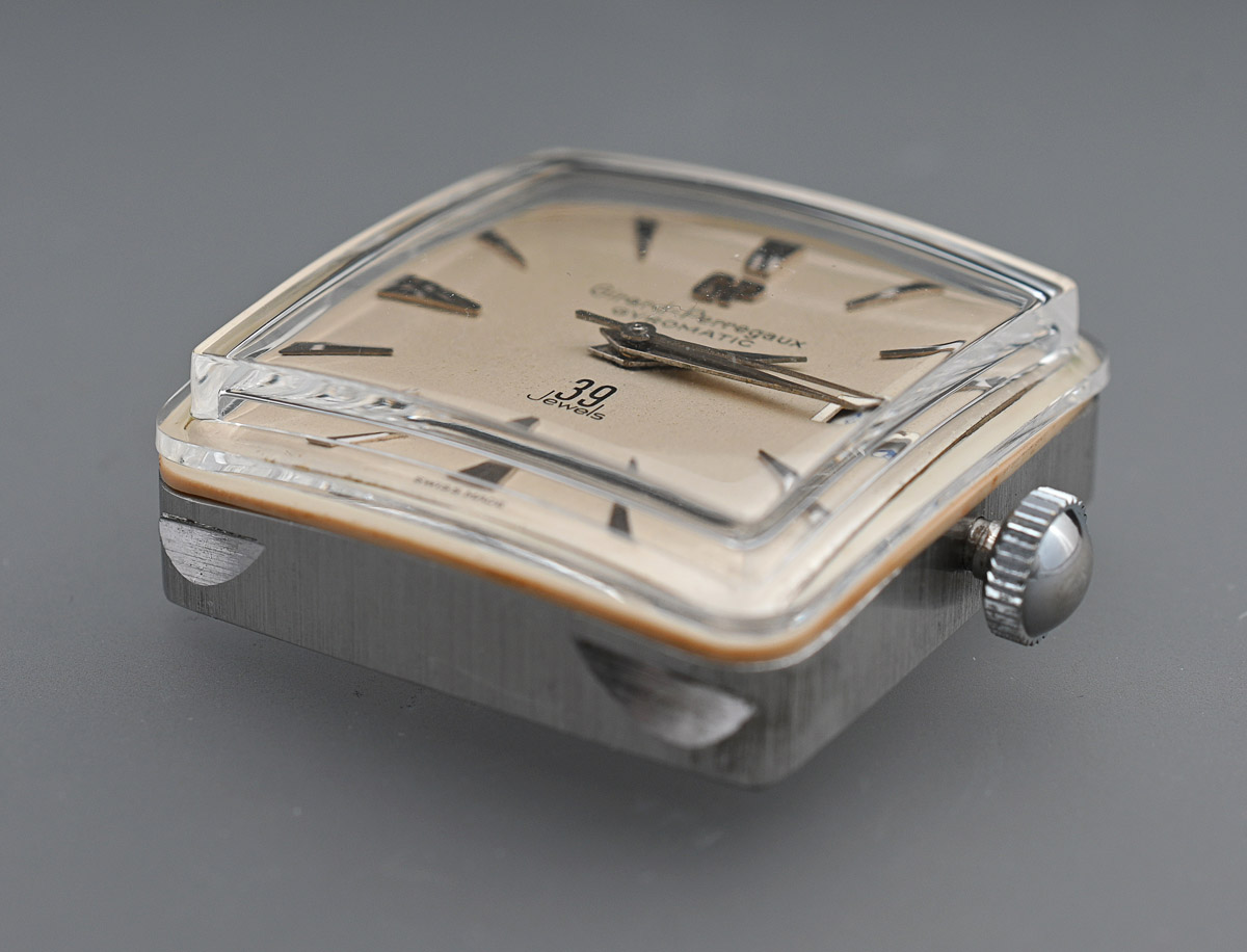
I think it is time to introduce the watch itself, a Girard-Perregaux Gyromatic 39 Jewels, dating from the late 1950’s. I can’t date it more precisely than that but knowing a little of the history of the original owner, I am guessing it was bought around 1959 in London.

The watch appears completely original all the way to its crystal which is fitted with a circular magnifier over the date window. You can see this feature in the detail from the opening advert from 1959.
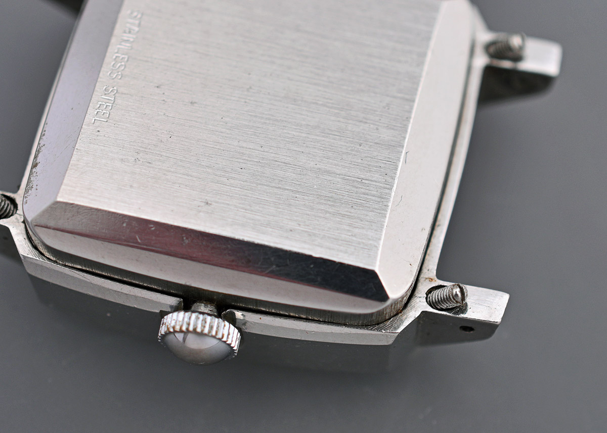
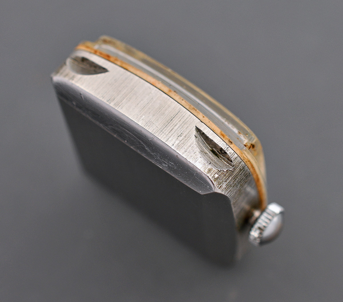
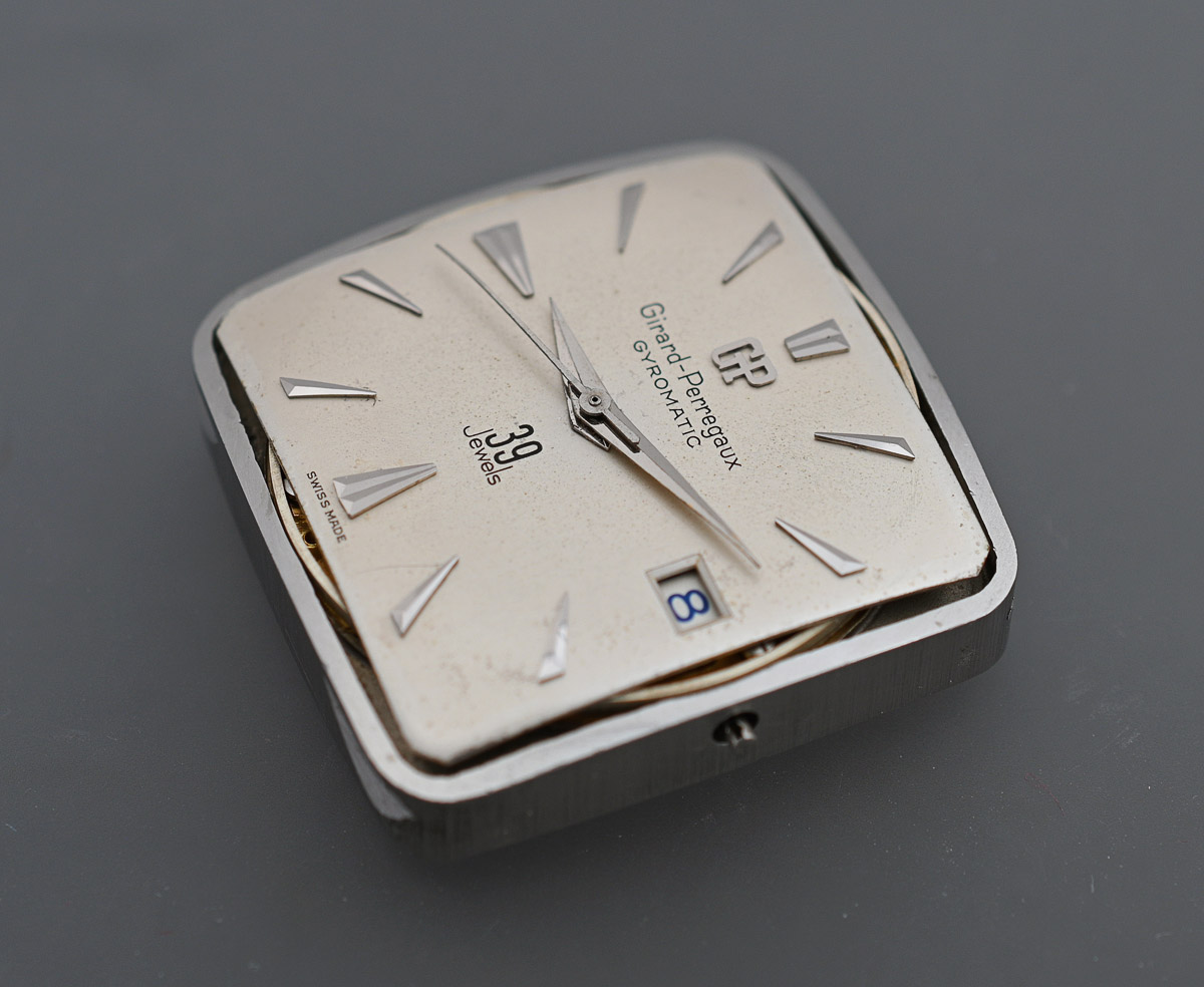
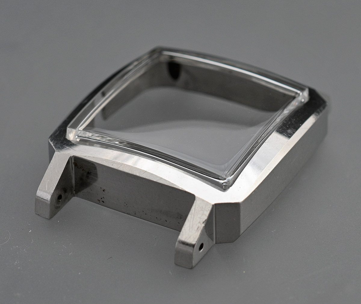
The case lines are crisp and the dial and hands display only the patina of dirt and wear associated with the handling of past watchmakers over the course of at least three previous services (the first in 1965, the second in 1976). The watch movement is housed in a square Brevet No. 189190 compression-fit waterproof case of a construction completely alien to anything we have encountered thus far in the blog. The upper case, such that it, serves only as a frame to house a lower, separate monocoque compartment that houses the movement, with the square acrylic crystal sealing the movement into the lower case by virtue of the force exerted upon it by the upper case housing.
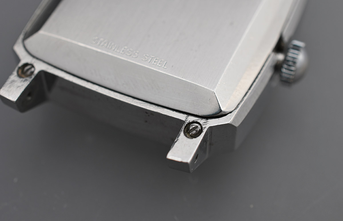
The clamping of the upper to lower case is achieved by means of four screws that pass through holes in the four lugs and gain purchase on shelves cut out of the corners of the lower case.
The movement is removed from the top of this lower case, there being no separate case back, and this requires first that the crown is separated from the stem.
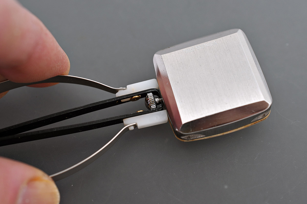
With the crown removed, the movement and crystal can be levered away from the case, the female part of the stem reversing out through the hole in the side of the case.

The crystal is fairly firmly adhered to the flat, beige gasket but both lift cleanly enough away from the dial to allow the two to be separated.

The hands were sitting very close to the surface of the dial and so I had to take special care to protect the dial when levering them off.
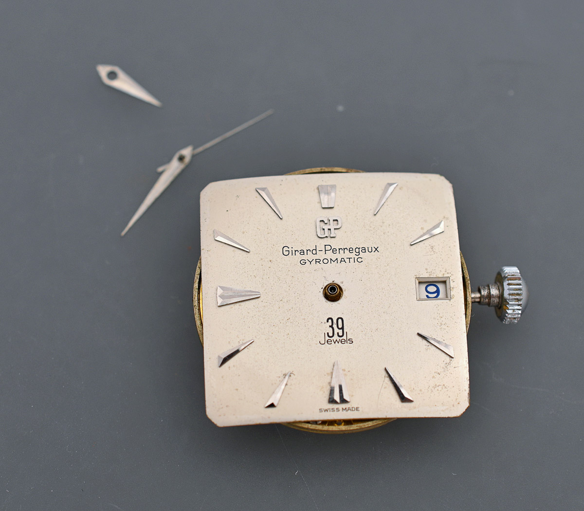
The dial is clamped to the movement by a pair of screws securing two dial feet at the 4.30 and 10.30 positions.
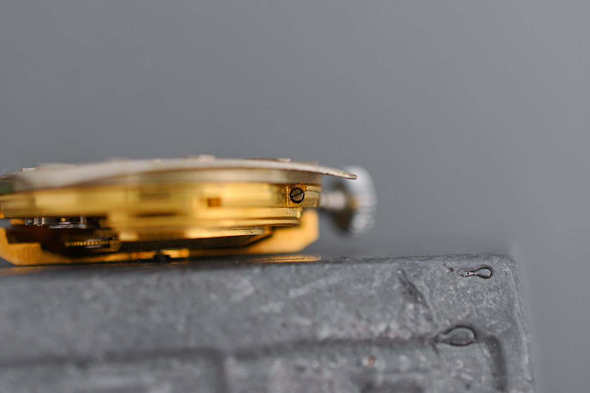
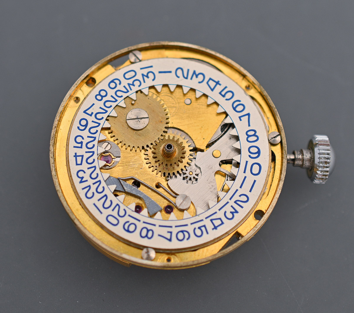
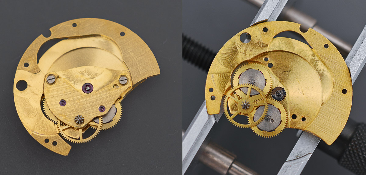
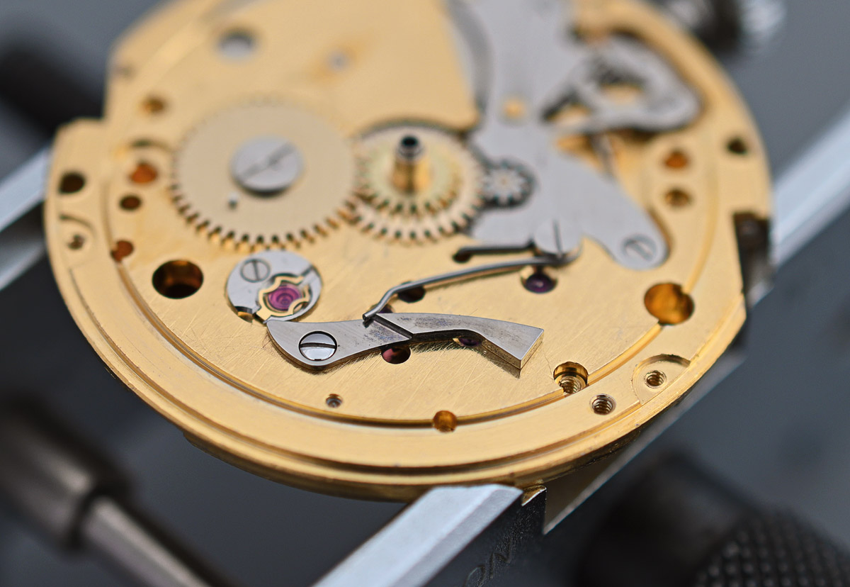
The photo above shows nicely the downwards curvature of the dial towards its four corners. Lifting the dial away reveals a calendar mechanism that looks quite conventionally laid out, with the upper of two teethed tiers on the hour wheel transferring motion to a date driving wheel which in turn acts upon the inner teeth of the date wheel once per 24 hours. The date wheel is indexed to the date aperture in the dial with the aid of a sprung date jumper.
The dial is supported by a dial ring that sits around the periphery of the movement and which just lifts away. I leave the calendar parts in place for the moment while I turn my attention to the train side to remove the rotor which is obstructing easy accommodation of the movement into my movement holder.

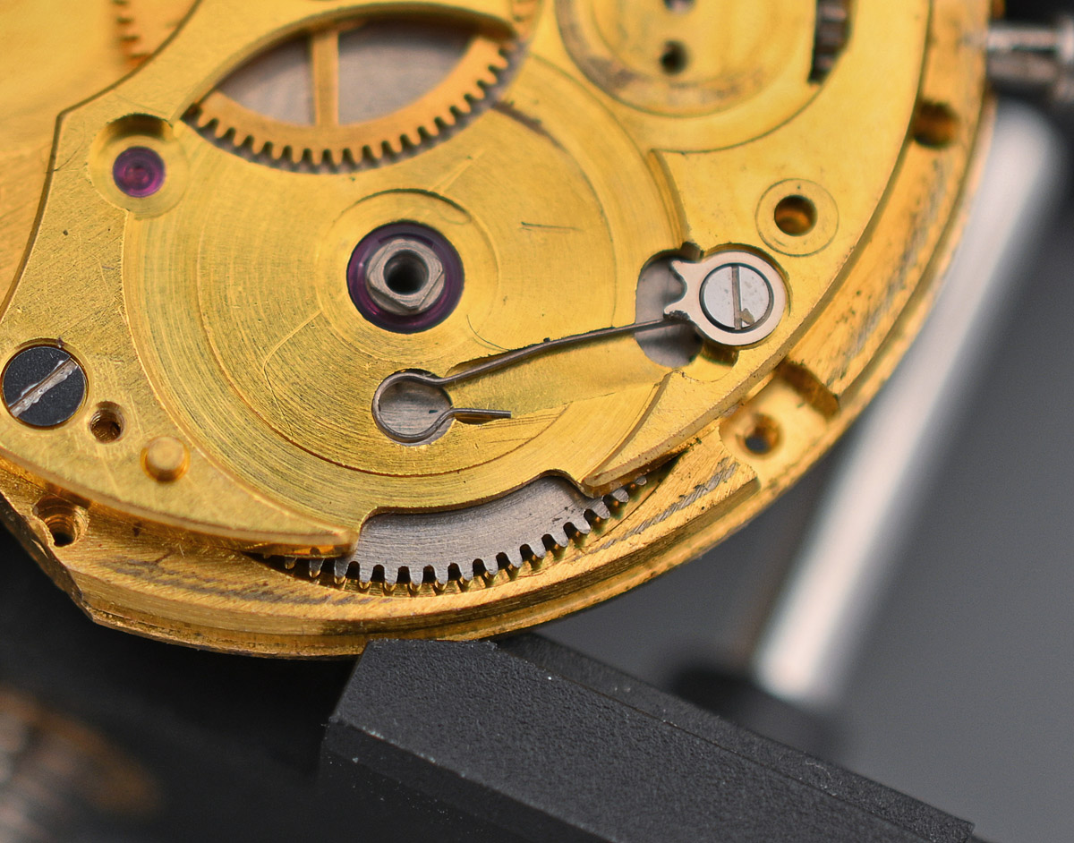
The rotor is secured to its post by a forked slider. It is removed by sliding the fork away from the pivot along the channel and then lifting the rotor away.
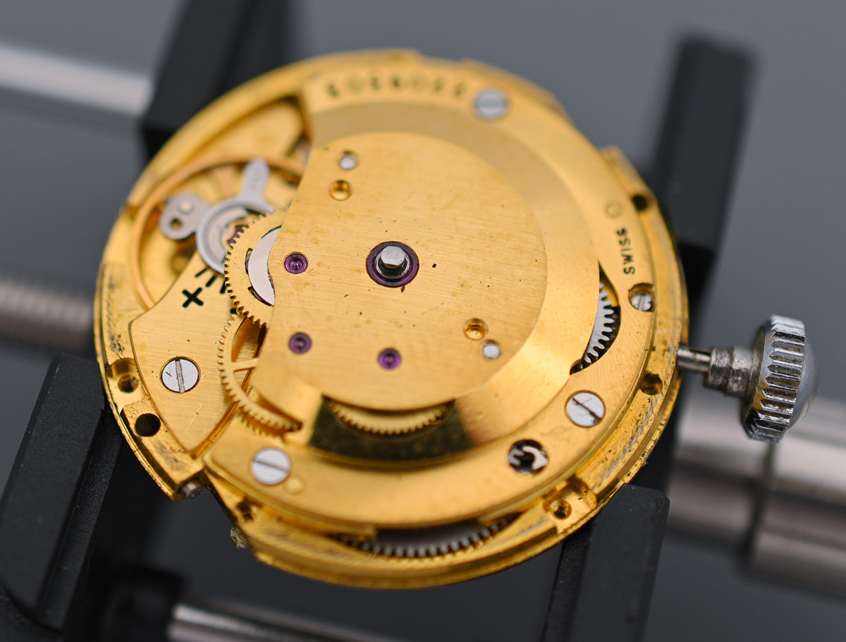
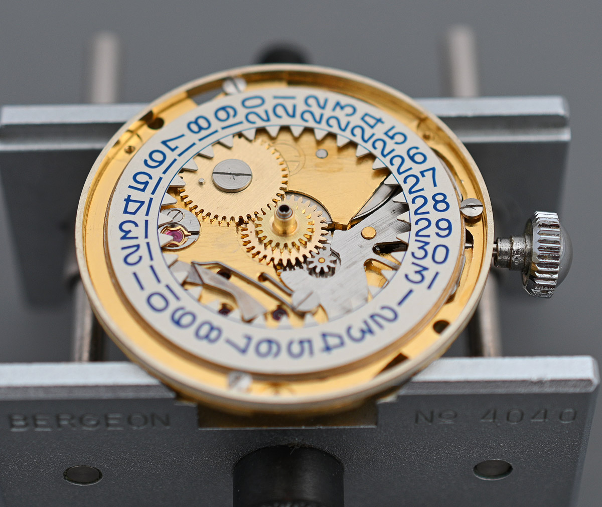
Returning to the calendar side, the next job is to remove the date disk which is held in position by three retaining screws.
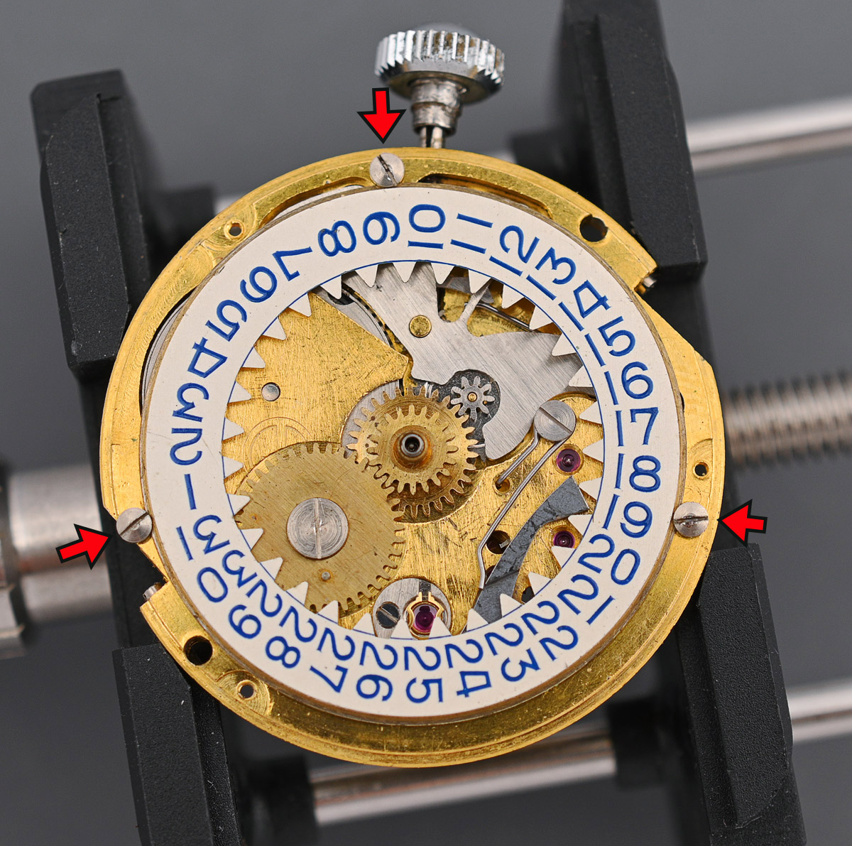
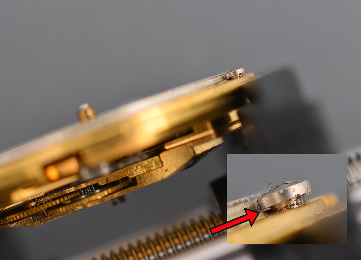
These screws do not make any contact with the disk in operation but are there simply to prevent the disk from becoming detached from the mainplate (see below).
With these three screws removed, the date disk can be lifted away, taking care to release the tension from the date jumper while doing so.
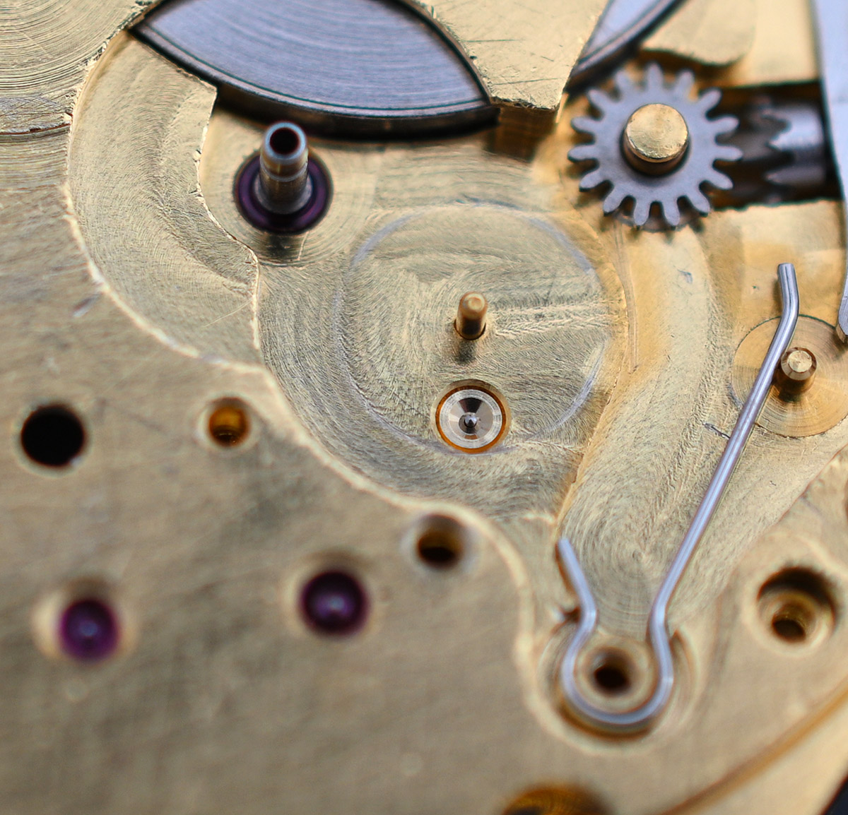
When I was running the watch through its paces, prior to starting its disassembly, I noted that the date changeover was sticky, with the date not lining up correctly with the date aperture in the dial. When I removed the jumper from the main plate, I discovered that the cause was dirty, congealed oil sitting between the jumper and the main plate surface, impeding its free movement.
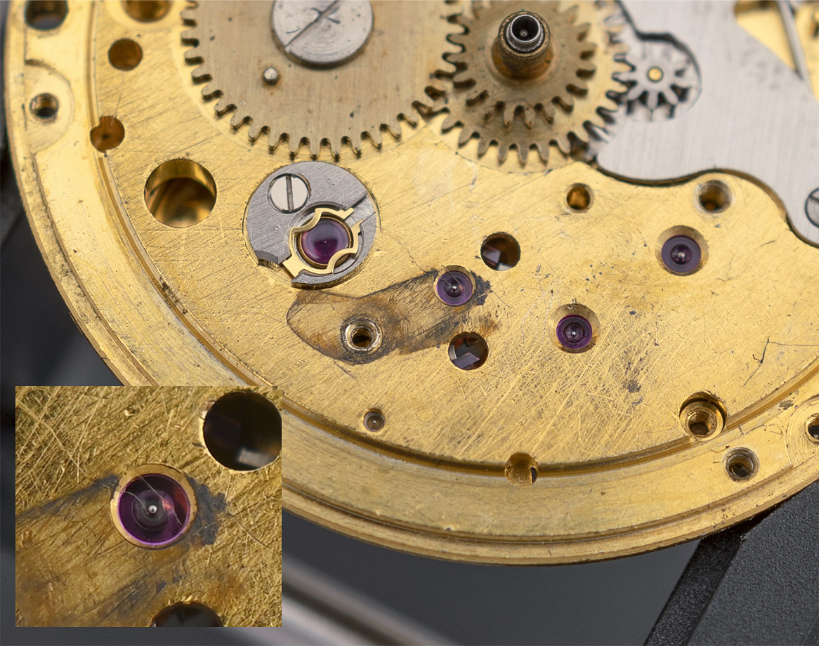
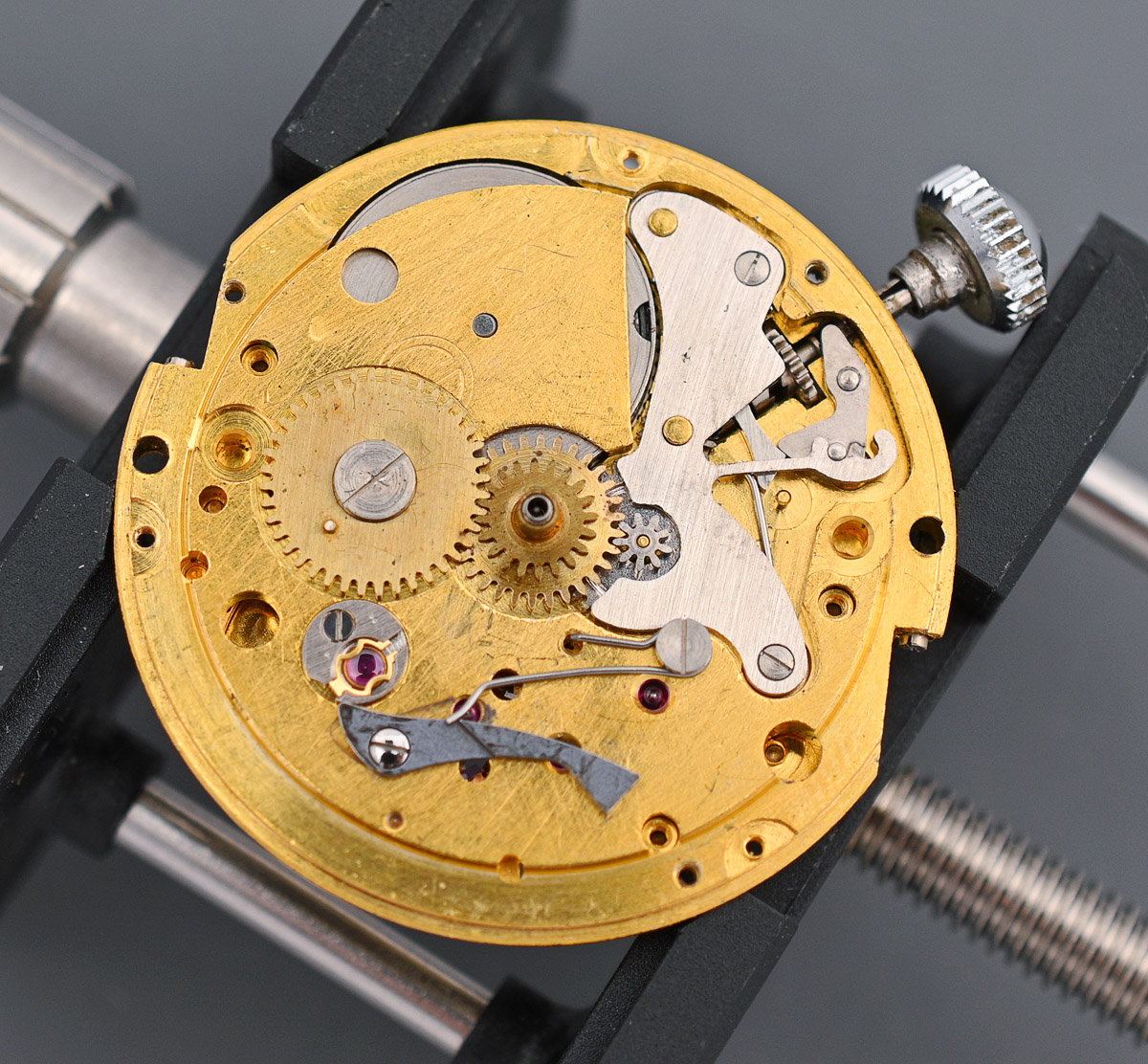
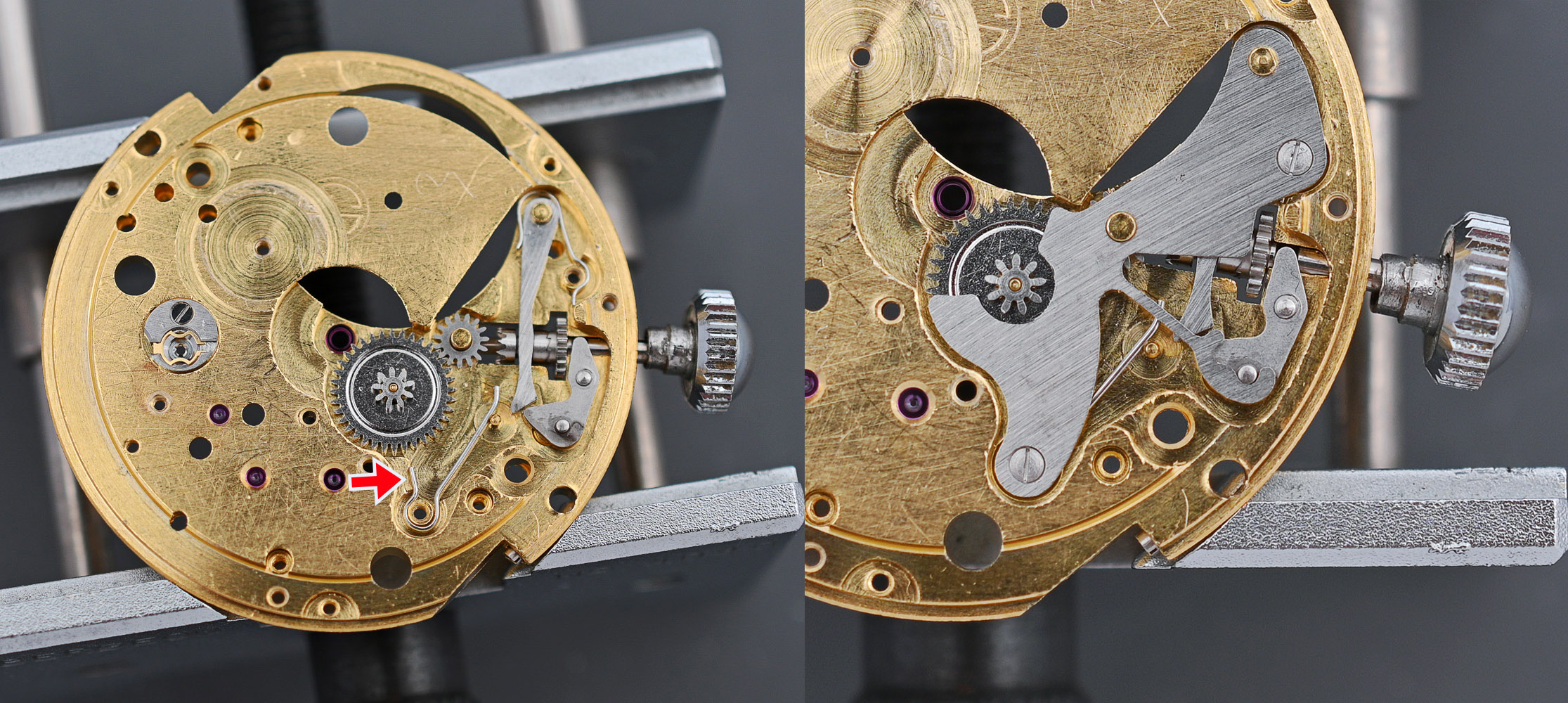
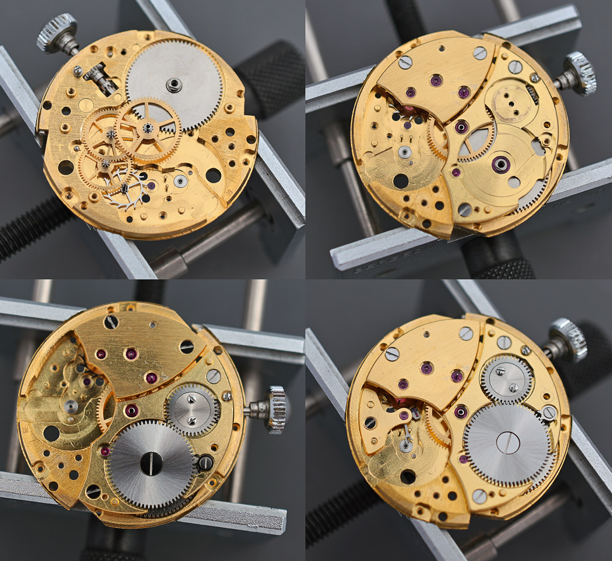
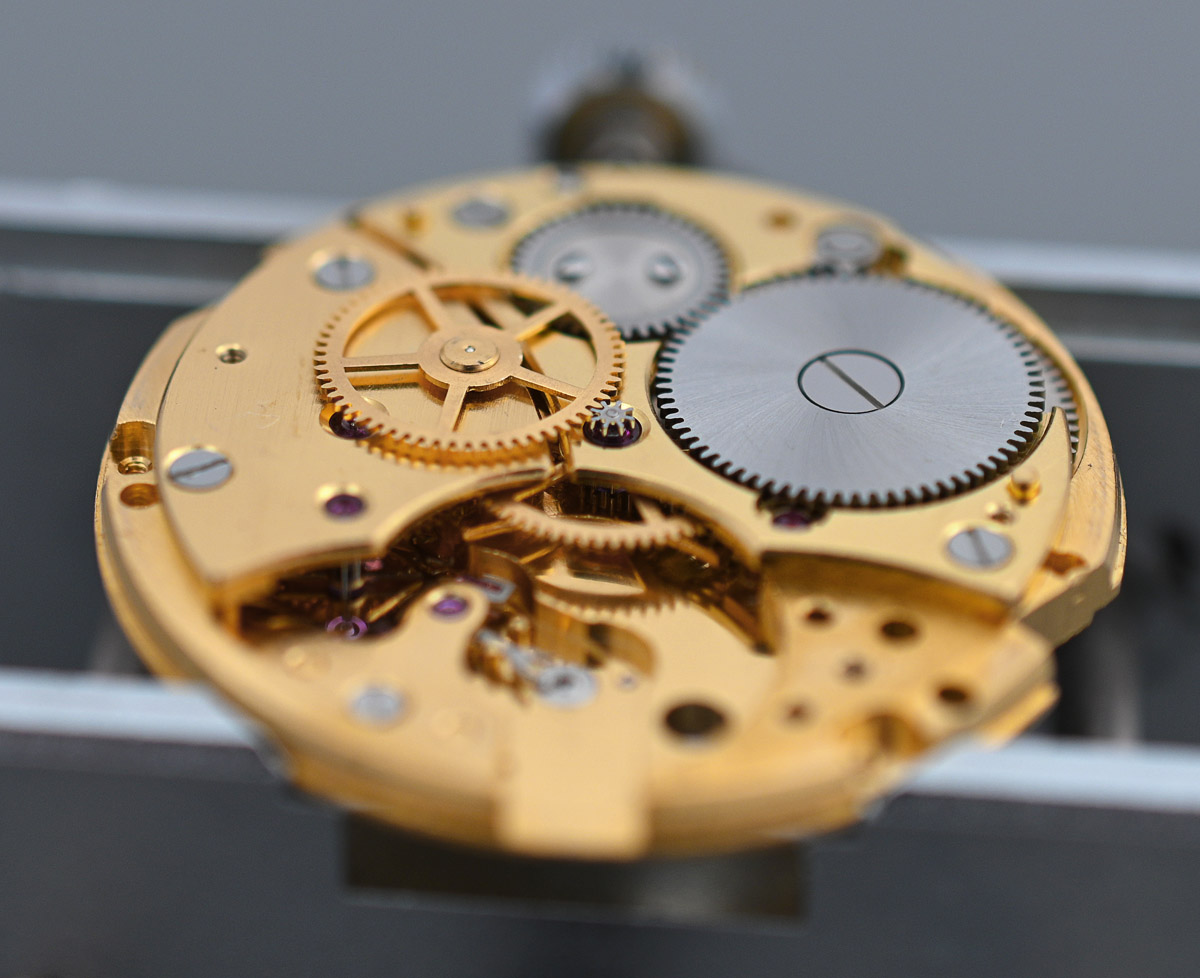
You may also be able to make out in the magnified insert in the image above that the situation will not have been helped by the presence of some fluff sitting above the pallet fork jewel setting. Turning our attention back to the train side, we start by removing the autowinder mechanism. This provides an opportunity to take a look at that dual reverser mechanism I described earlier. The rotor gear sits at the middle of the bridge (right hand image, below) and engages with the outer crown wheel teeth of the lower of the two Gyrotrons. That Gyrotron engages with the second Gyrotron, again through their outer crown teeth and then one or other of the two engage with the winding wheel, sitting between them, via their hub disk gears.
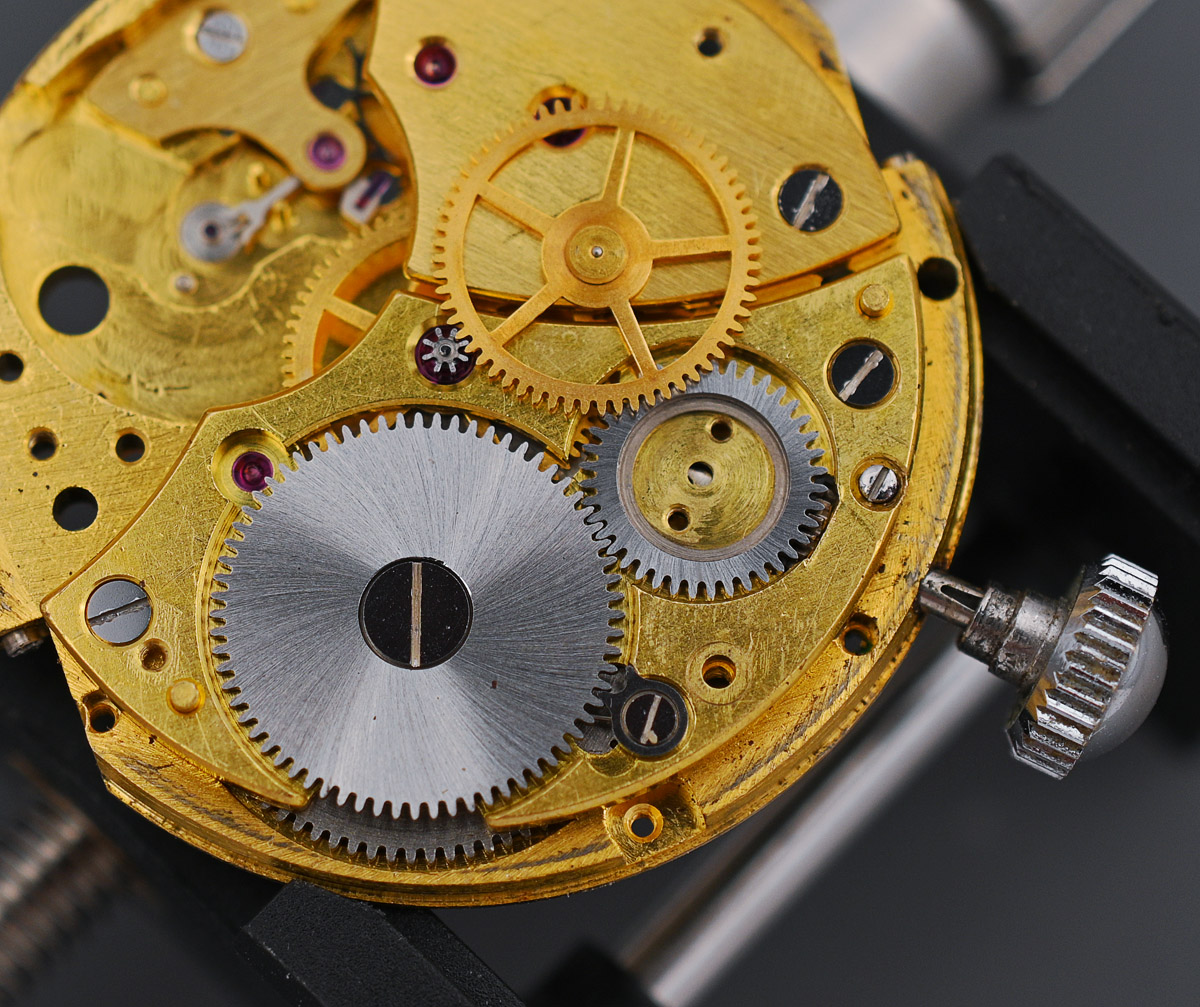
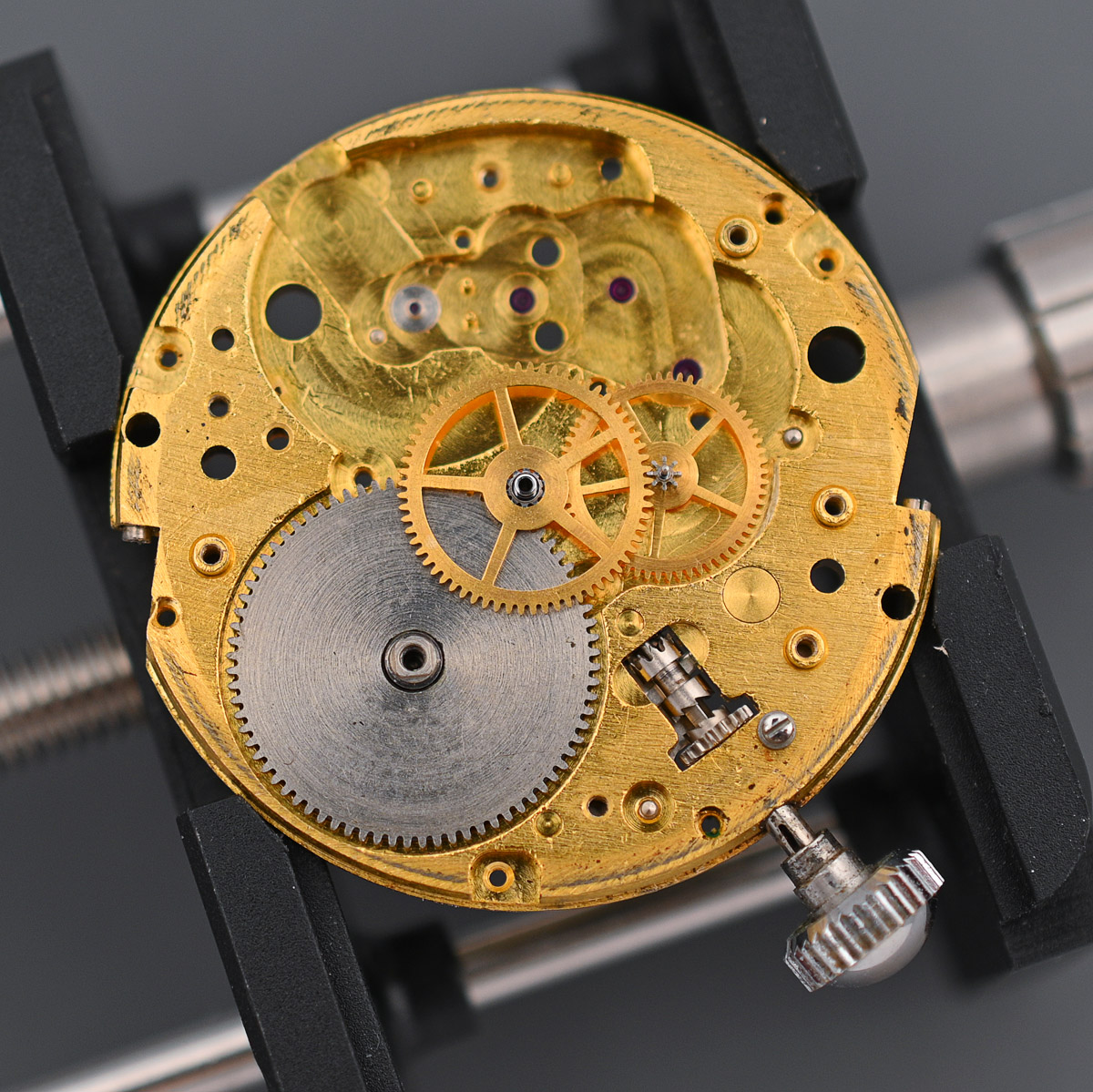
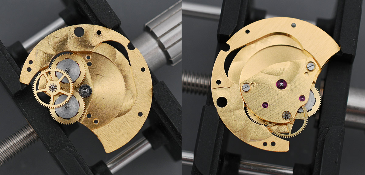
Having removed the autowinder mechanism, the origins of the base movement become clearer.
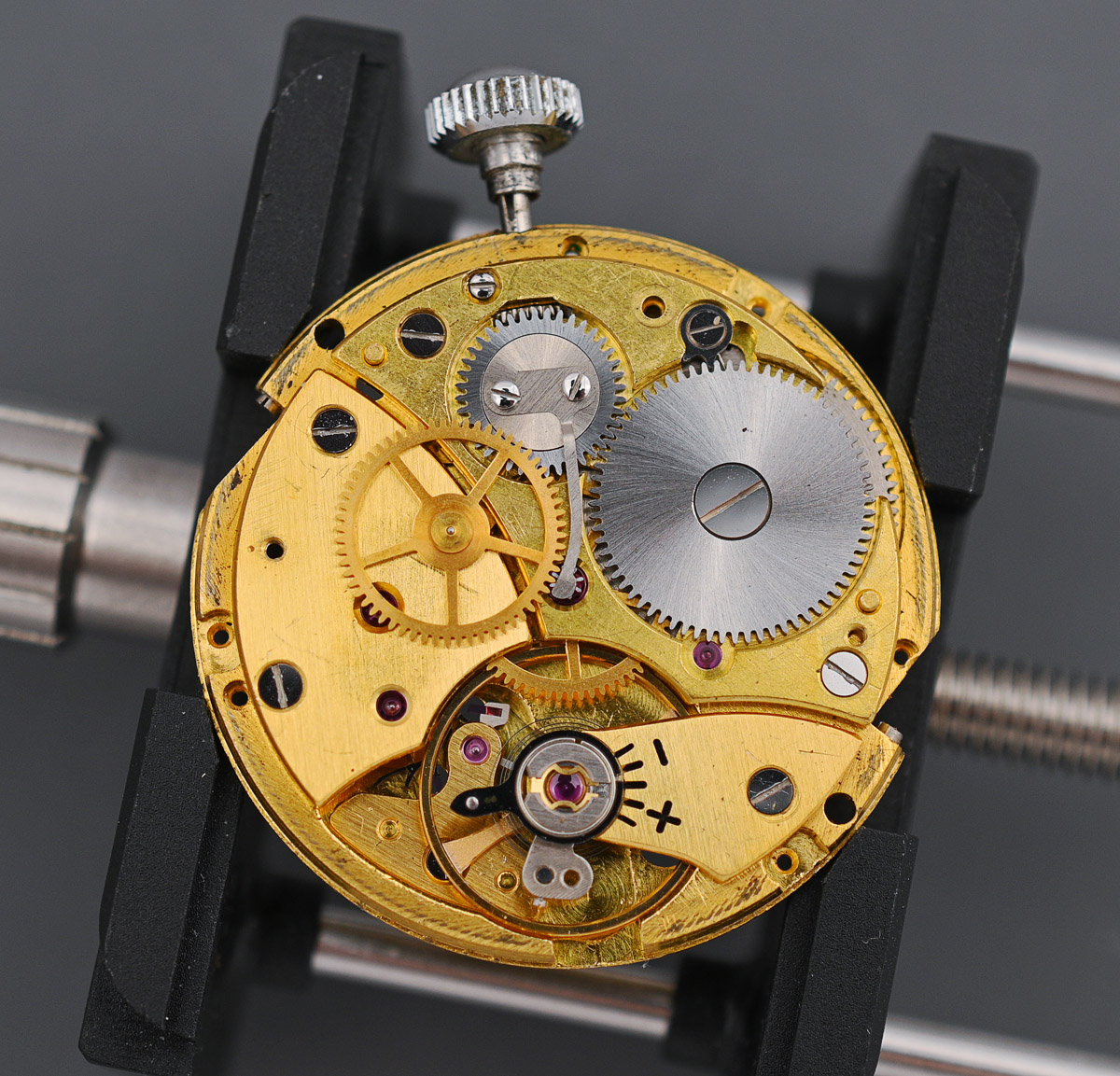
This is a hand-wind movement at heart and looks identical to the Peseux 335/GP 20 hand-wind movement shown towards the beginning of this article. The only differences are the jewelled bearing serving the winding gear, just south of the ratchet wheel and the tapped holes in the bridges to accommodate the screws to attach the autowinding mechanism.
First step before removing the balance is to take out the Incabloc setting.
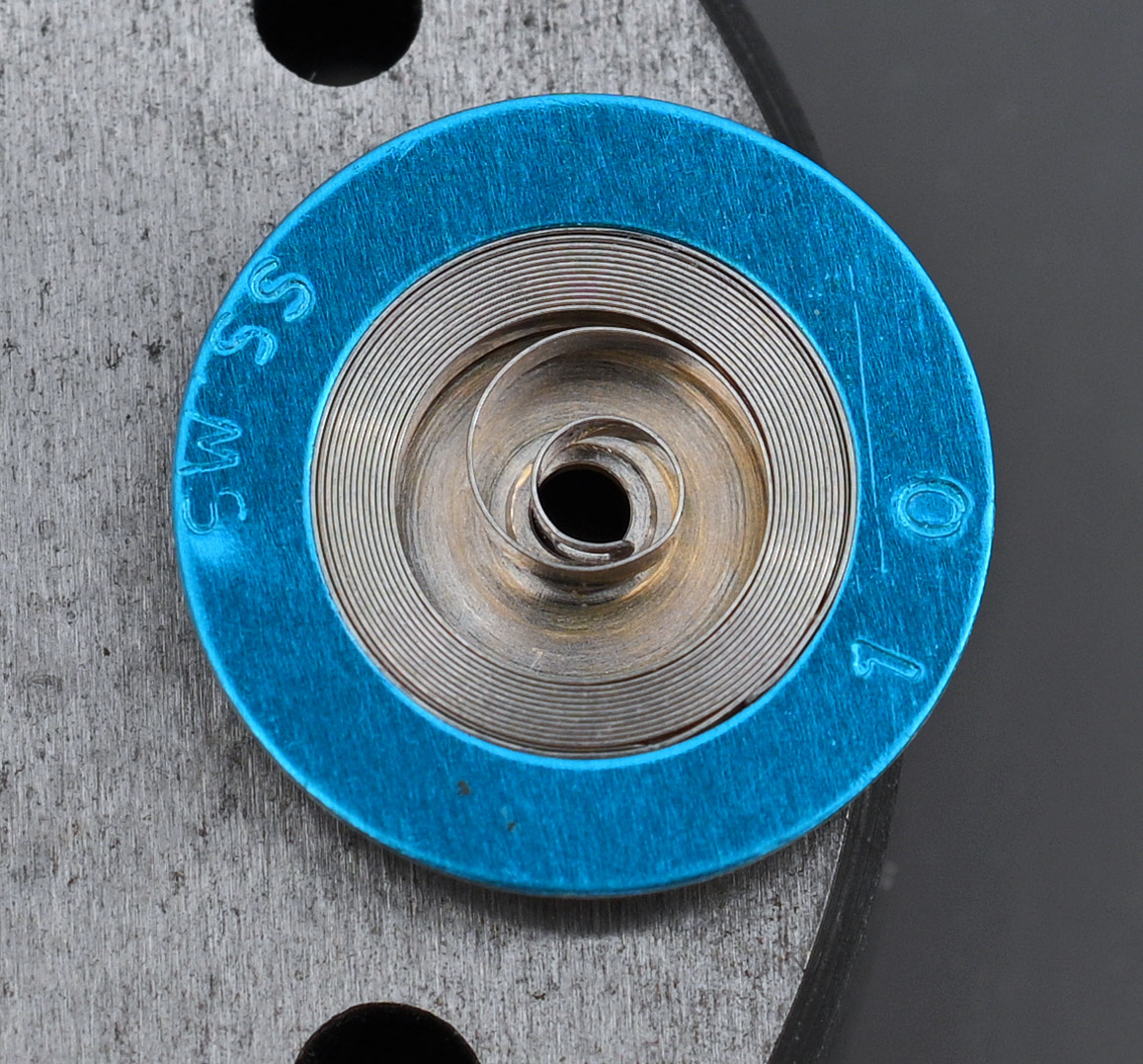
The balance hairspring looks to be in excellent condition.
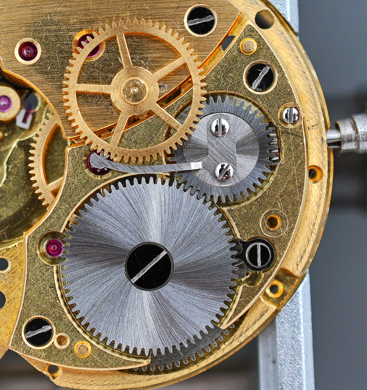
The tension spring holding the centre seconds pinion is secured to the centre of the crown wheel and so the former and latter come out next.
You can see from the photo above that the centre seconds pinion is driven by an intermediate wheel mounted on the third wheel shaft emerging from the train wheel bridge. This intermediate wheel needs to be removed before we can remove the train wheel bridge and expose the going train.
The ratchet wheel comes off next, exposing the click spring and click. We need to take care not to lose the former!
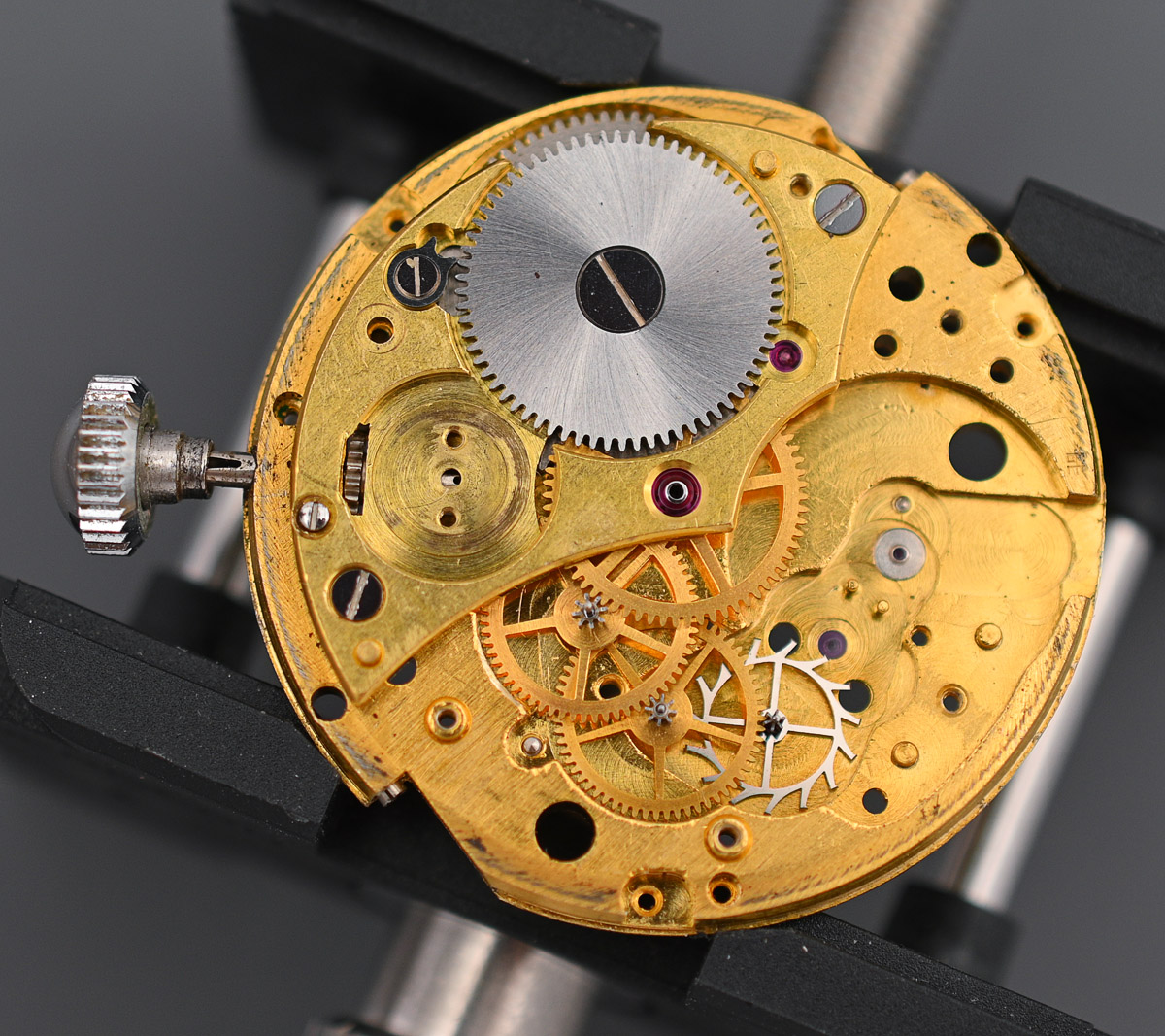
With the barrel bridge removed, we are just two or three steps away from having fully stripped the train side.
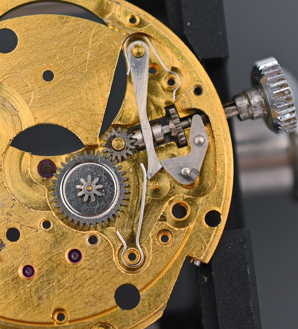
Back to the dial side and we can resume disassembling the setting parts, having first removed the cannon pinion, releasing the centre wheel from the other side.
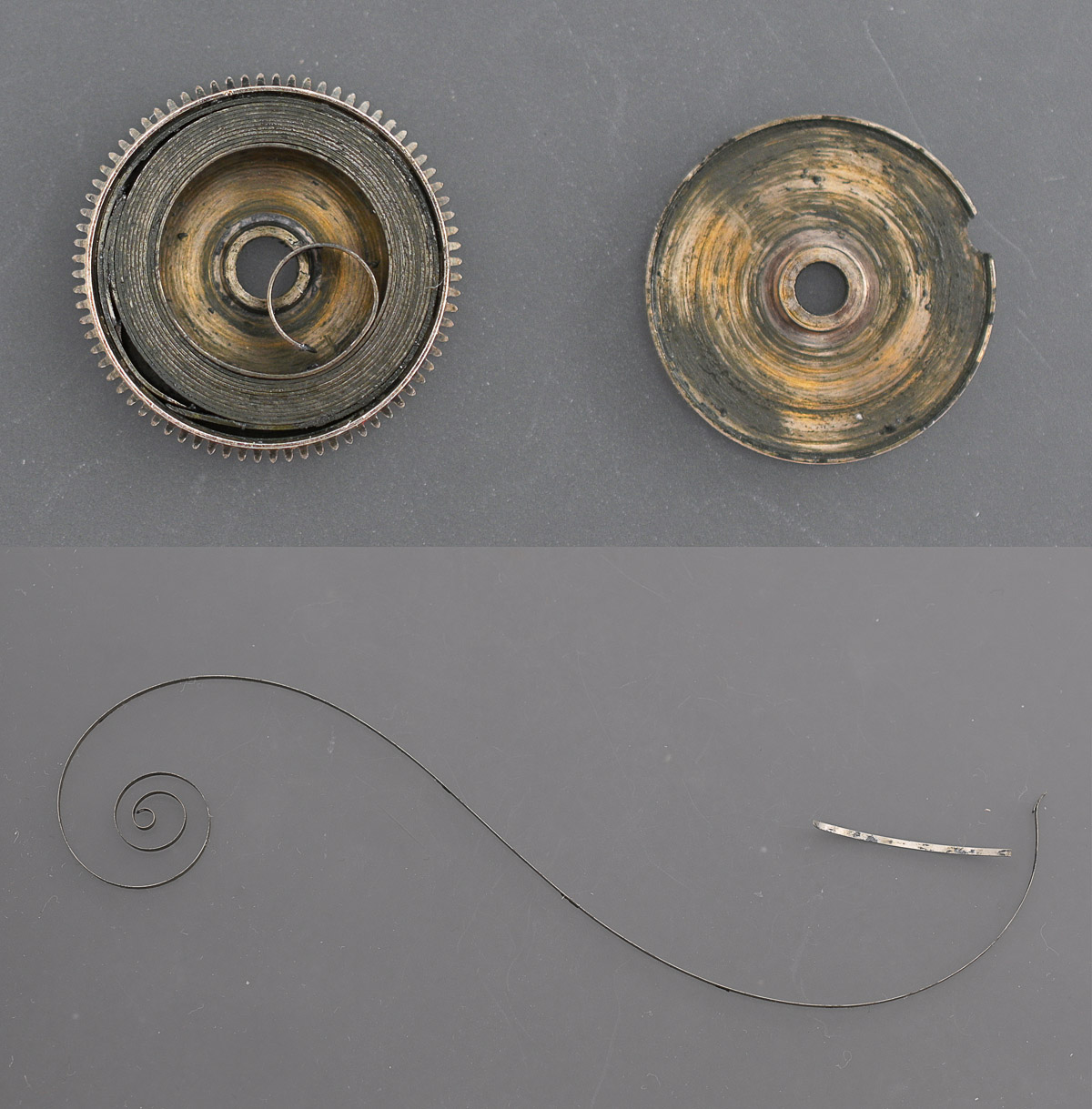
The last order of business is to open the barrel and appraise the mainspring. To my surprise, extracting the mainspring revealed that it was broken at the tail. I was surprised at this discovery because I was able to wind the watch pre-service to get an idea of how well it was running. Clearly, there was still enough resistance to slippage that the spring was able to hold a decent amount of wind.
Everything is ready to be cleaned at this point and so we re-join the action as we embark on the first steps to reversing everything that has come before. We begin with the setting parts, taking great care to make sure the yoke spring is correctly located (indicated below, left) before tightening down the setting lever spring.
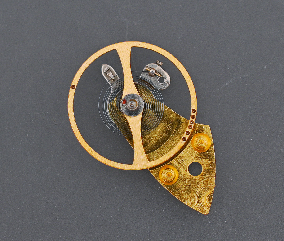
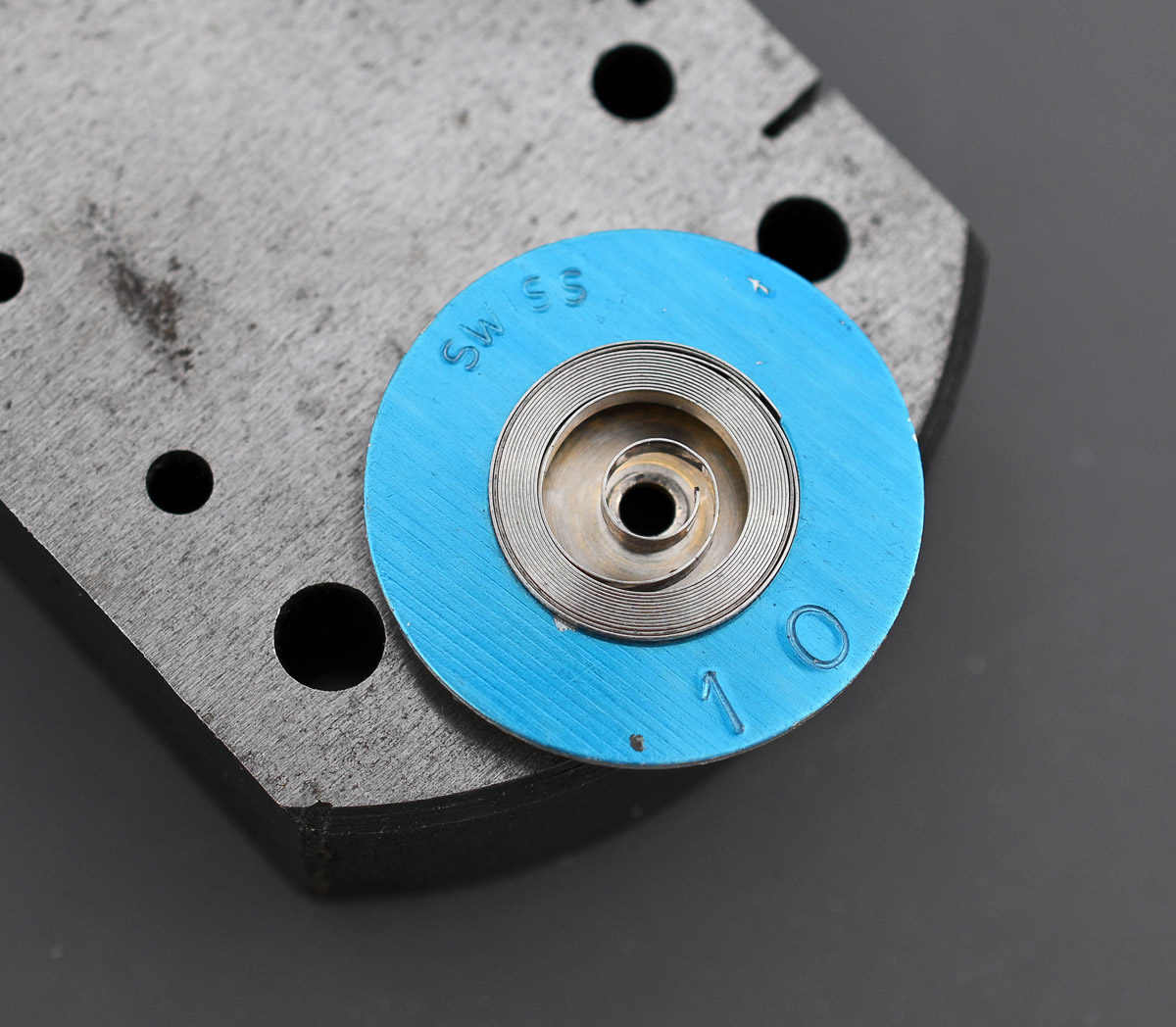
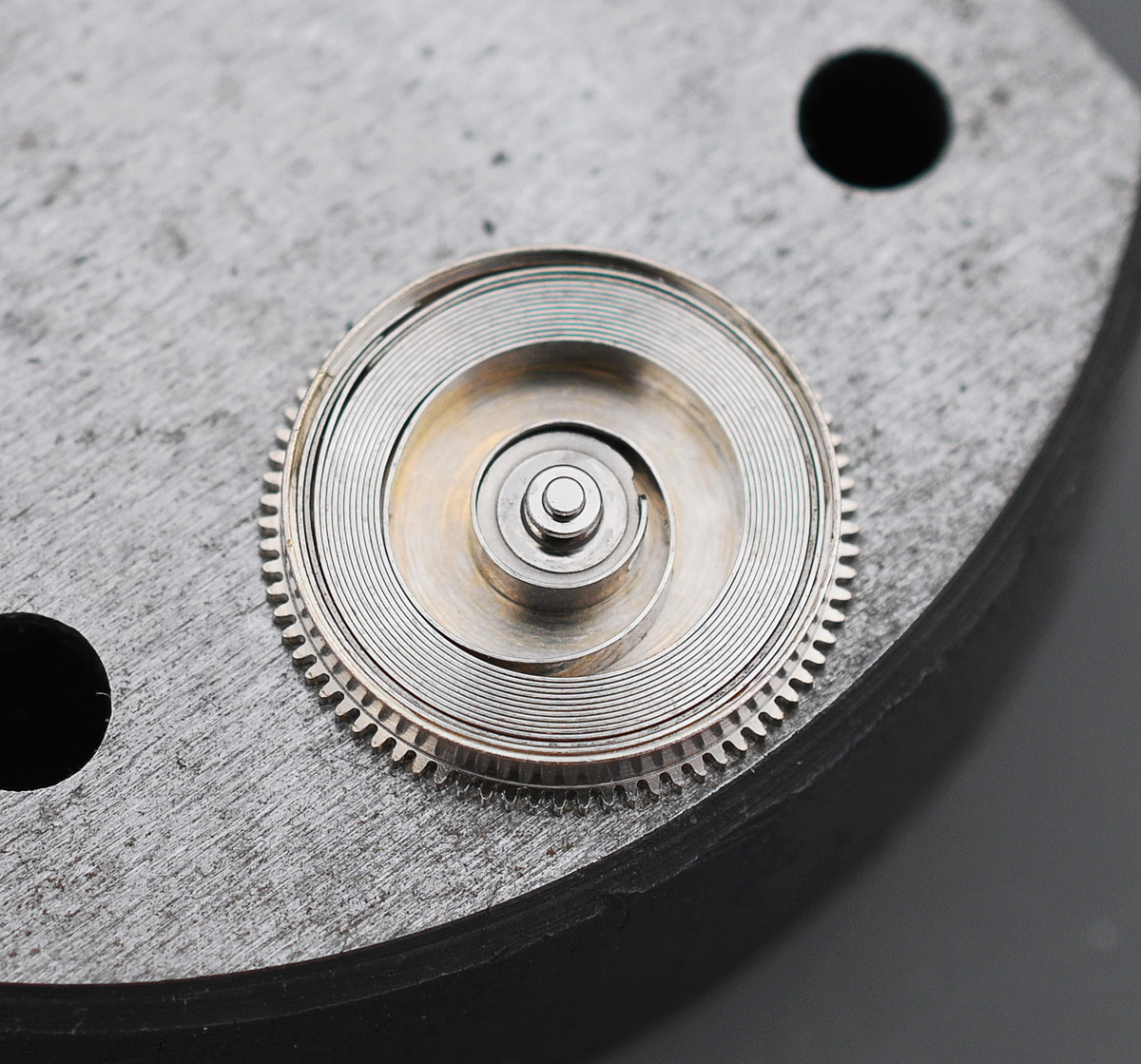
I choose to tackle the autowinder mechanism next because at this point I was still waiting for a supposed 48 hour packet post containing a new mainspring to arrive but which actually took closer to 144 hours. So in the meantime, I got on with what I could get on with! Before we assemble the autowinder, let’s take a closer look at one of those ingenious Gyrotrons.
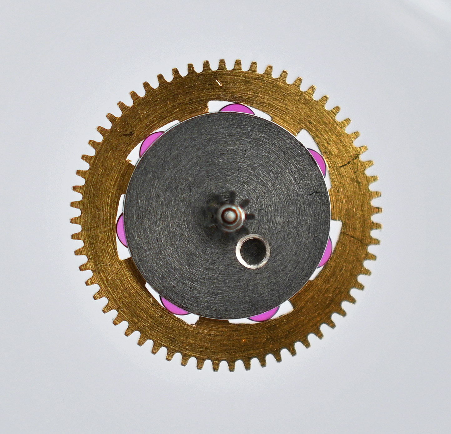
You can quite easily see those seven perfect disks of ruby, each sitting within its own shaped chamber, within which it moves to one end or the other depending on the direction of rotation. In reassembling the mechanism, these jewels remain unlubricated to ensure that their free movement is as unhindered as possible.
The choice of replacement mainspring required some research and a little careful thought. Needless to say, original replacements are no longer available and so we need to identify a generic replacement as close as possible to the original specifications. The excellent Ranfft movement database reports that the mainspring dimensions for the GP 22.09 are 1.25 x 0.12 x 270 x 9.5 mm while Jules Borel recommends the GR 3239-X whose dimensions are 1.30 x 0.095 x 360 x 9.5. The very different spring thickness and length of the two suggests one of them is not to be trusted! My measurement of the original broken mainspring yields the following: 1.25 x 0.11 x 300 x 10 which suggests Ranfft to be the more reliable source of information in this instance. In surveying the available options on Cousins website, I identify two candidates:
GR3699X 1.25 x 0.11 x 320 x 10 mm
GR3141X 1.25 x 0.115 x 340 x 10 mm
The second of these is marginally thicker and so ought to provide a slightly higher amplitude but for the moment I order one of both and wait nearly a week for them to arrive.
The GR3699X was the closest match to my measurements and so I lined that up as my initial choice.
Unfortunately, the diameter of the inner loop was far too small to accommodate the large barrel arbor and so my attention turned to the GR3141X whose inner loop appeared far more accommodating.
Here it is fitted.
I lubricated the barrel walls with five spots of 8217 and the mainspring itself with a couple of dots of 8200 administered to the top of the fitted mainspring. Reassembly of the gear train proceeded smoothly as far as refitting the pallet fork, but not yet the sweep seconds pinion and its tension spring. For the moment therefore, the crown wheel screws are fitted but will need to come out again when it comes time to fit the sweep seconds spring.
At this point I set about lubricating the gear train bearings but when I arrived at the dial side third wheel bearing, I realised that it was hidden behind the minute wheel! Clearly, the main plate bearing or the third wheel shaft needed lubricating before fitting but I wasn’t going to disassemble everything on the train side to accomplish that and so instead removed the setting lever spring and minute wheel to gain access to the bearing.
Mis-steps are all part of the learning experience when exploring new territory and this one has caused nothing more than a five minute diversion. Moving on, we can continue to work on the train side. First, the intermediate wheel mounts onto the third wheel shaft, and then the sweep seconds pinion.
And now we can remove the two crown wheel screws, place the sweep seconds tension spring and refit.
The Incabloc setting on the dial side lays the ground for refitting the balance and fitting its Incabloc.
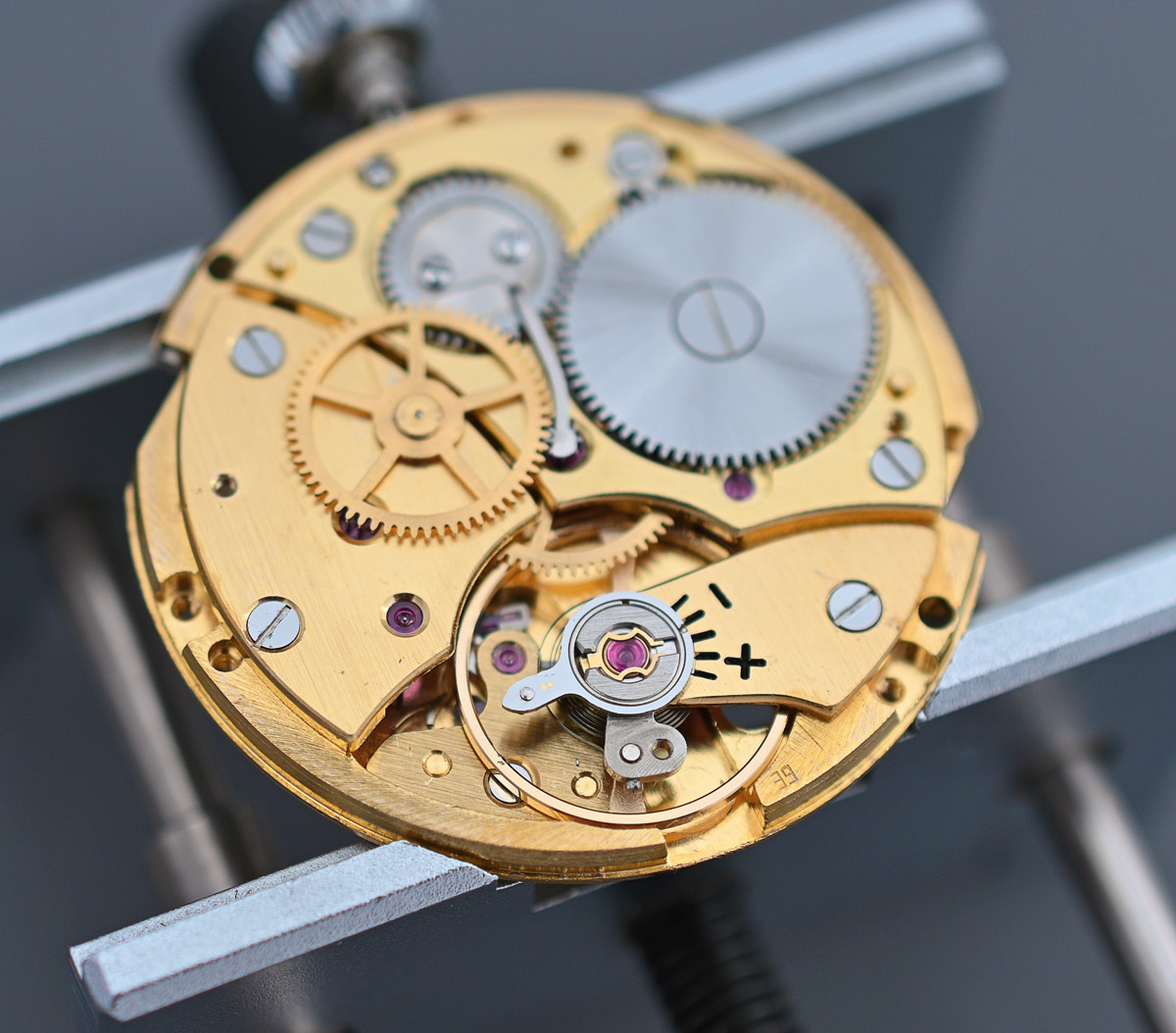
Some power in the mainspring, and it’s away and running.
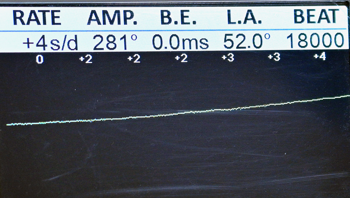
I spent a little time tweaking to get the watch working consistently well in different positions and after one or two cycles of winding to full power and running down, the movement settled and achieved excellent amplitude, beat error and positional consistency. Here is a snapshot reading, dial down.
Once I was satisfied that I’d worked out all of the gremlins, I felt able to move on to fit the autowinding mechanism.
Back to the dial side and we can refit the date jumper and its spring.
And then fit the date disk and the dial ring.
At this point we are ready to fit the cleaned dial and test that the date advances correctly.
Fitting the hands required a little care. The hour hand sits close to the dial surface and its tip needs to clear the applied GP sitting shy of the 12 hour marker. As I fitted the hour hand I realised that it curves upward naturally which I presume is how it was designed to be originally. The minute hand however needs to clear the downwards inner slope of the crystal and has a gentle downwards slope towards its tip, as does the seconds hand. You can possibly make out the contrasting curvatures of the three hands in the photo below.
The movement is now just one step away from being ready to refit back into the lower case, requiring just the rotor to be fitted and the crown detached from the stem.

Having removed the crown, the movement can be eased back into the now cleaned lower case.
The crown is pressed back onto the stem and the cleaned crystal gasket laid around the edge of the dial.
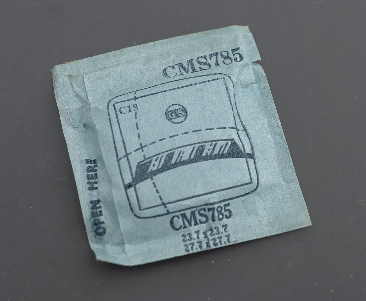
The rate determining step to even contemplating a start on this project was to identify and locate a replacement crystal. My starting point was one of complete ignorance and some determined foraging was required, first to figure out the correct crystal and then to locate some stock. I started by performing a Google search based on the Brevet case number 189190 and this threw up a link to a blog post showing a photo of a Gallet clamshell crystal in its packaging with part number PA 470. I had a back and forth with a watchmaker friend who observed that the model number for the crystal shown in the blog was for a circular G-S Supplies crystal not square. G-S have an excellent online e-catalogue and so I had a leaf through that until I came upon a section listing Military Cylinder Fancy Crystals, one page of which occupied by square crystals whose model numbers have the CMS prefix. A measurement of the original crystal appeared to confirm that CMS785 is of the correct dimensions for the GP.
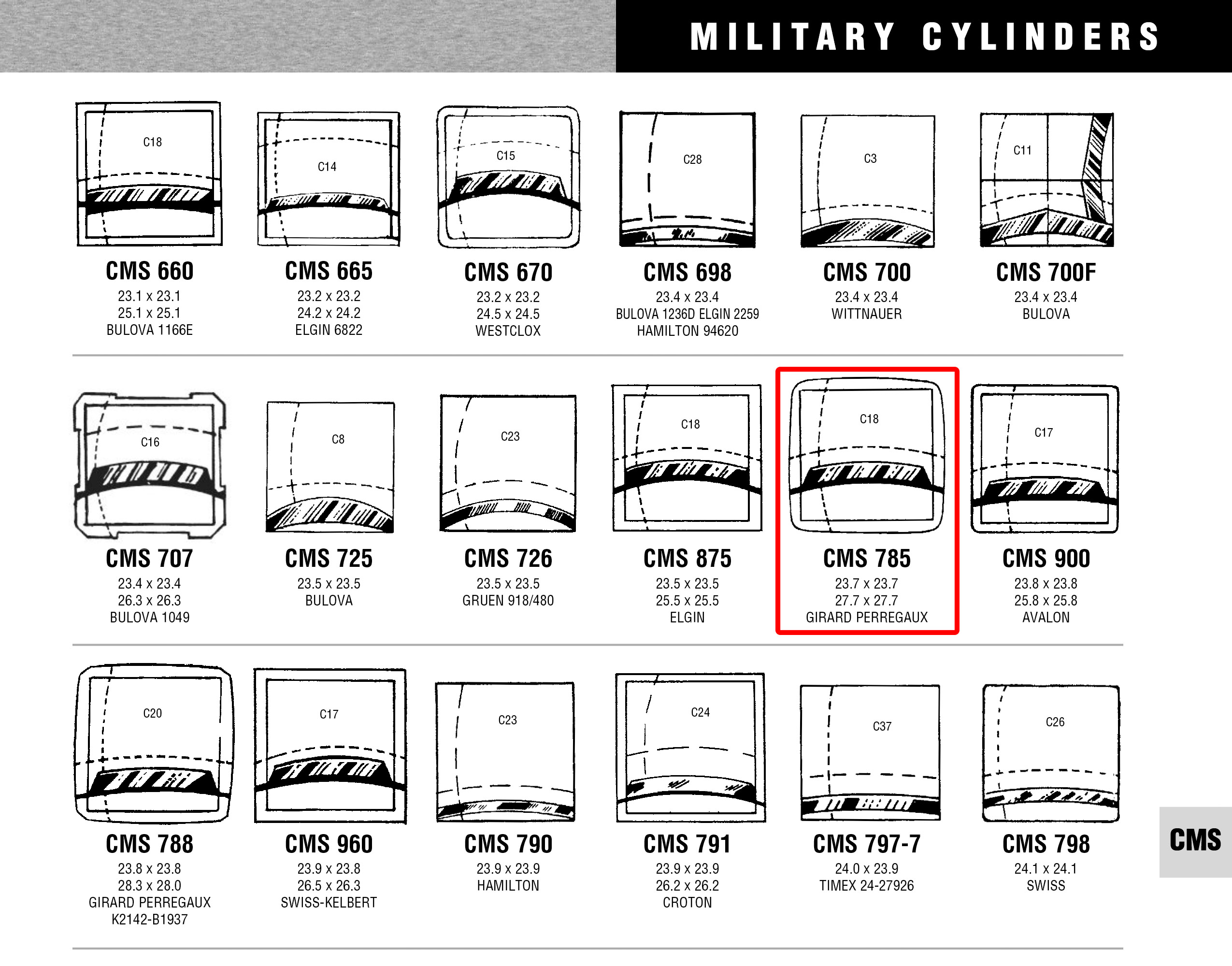
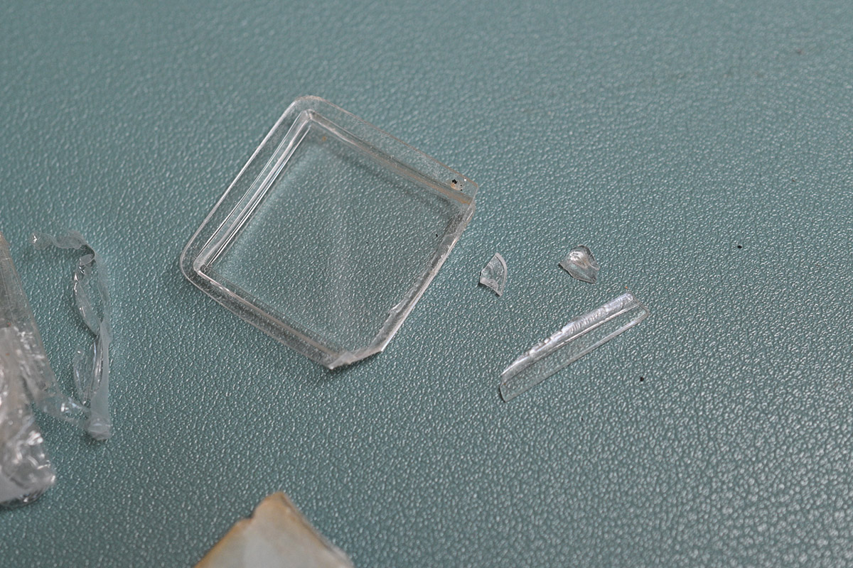
I was further reassured by the Girard Perregaux text below the entry in the catalogue. Having apparently identified the correct crystal, a short while later, I found an auction on eBay from a European seller for a new old stock G-S CMS 785 for a very reasonable price and so I placed my order. A week or so later, the crystal arrived in a flimsy postcard-sized envelope with almost no protection. When I opened the package I was faced with this.
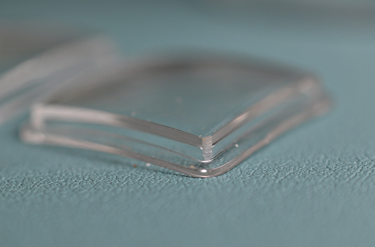
The seller agreed to send a replacement and a week or so later it arrived, also in a flimsy envelope with minimal protection, despite my encouragement to use more robust packaging this time. Fortunately, the replacement arrived undamaged by its journey. Unfortunately, it was clear that the replacement was in fact not new but used, all four corners having been shaved, presumably from fitting to an undersized case at some point.
I abandoned any further attempts to extract either a refund or suitable replacement from that seller but after a few weeks, a refund notification did appear from eBay. In the meantime, I looked for alternate suppliers and located a source in the USA called Tip Top Crystals. I had to pay a little more than but of course it was having to come all the way across the Atlantic. A week or two later a well cushioned package arrived containing not one but two CMS785 crystals in perfect, new condition. They had thrown in a second gratis. How nice is that?
A test fit confirmed that this was the correct part and that the hands cleared the underside of the curved crystal.
I found that the best way of completing the assembly of the watch from this point was to fit the crystal to the upper case first and then lower that onto the monocoque lower case.
I did it this way because it was easier to jiggle the crystal into the rather tight fit of the case separately rather than having to force the issue with the crystal already seated on its gasket. Once the two casing parts are together, we can tighten down the four case screws to ensure a good compression fit between the crystal and gasket.
And finally, we find ourselves with a complete watch.

The final order of business is to select and fit a suitable strap.

This has been a hugely enjoyable project, in part because almost every step has been into the unknown or unfamiliar, but also because it is one of the oldest watches that I have worked on yet one whose history is not a mystery because it came to me via the daughter of the original owner. It is a watch of high quality whose movement performs really quite spectacularly well in spite of it having lived well for 62 years.

And yet, this is a watch that is guilty of skirting the edges of hyperbole in proclaiming its elevated jewel count quite so loudly. In essence, this is a 17 jewel movement, albeit a rather lovely one, but one fitted with an autowinding mechanism that comfortably doubles the total jewel count. Arguably, none of those additional 22 jewels contribute to the timekeeping of the watch and yet every one of them plays an active role in its function. Was it necessary to use jewel rollers rather than, say, steel ball bearings? That, I cannot say, but what I can say for sure is that every one of them is in perfect condition after 62 years and the mechanism appears still to perform flawlessly. I am happy therefore to give it the benefit of the doubt and declare this an authentic and loveable piece of late 1950’s technical innovation and design.

I don’t know why, but I loved this breakdown and build-up, I had no vested interest, ie no ownership or previous knowledge of model but I was engrossed. The winding mech held my attention long enough for the epiphany of wow I get it, which is unusual as I can be quite dense in relation to, ‘this turns that way and turns this thing the other way.
The setting mech is still a bit of a mystery but perhaps another time; looking at your posts always makes me think,’ jeez there ain’t half been some clever barstewards’……chuckle ¡
Thank you! Your comment is appreciated not least for its introduction of a reference to the mighty Mr. Dury and his Blockheads!
A very interesting article. I have a similar watch – in gold (which I imagine makes the seal more difficult), no date function – and while I knew the basics of the structure of the case I was intrigued by the specifics.
My watch is extremely accurate, having been serviced immediately I purchased it (with previous service history unknown). It achieves +/- 3 seconds a day consistently over a month which I consider remarkable for a watch 60 or more years old.
Thank you Stephen. Yes, 8 have also been really impressed in absolute terms with how well this movement runs without any allowance for the fact that it is over 60 years old.
Love your attention to detail. Thanks
I’m glad you enjoyed it. Thank you!
Wow….what a nice piece…lots of design work on the auto wind mechanism….i almost feel sorry for the designers compared to seiko’s majic lever system…but it certanly looks good…nice blog entry as usual…d.
To he honest, I think this is a rather more elegant design than the magic lever but in both cases, clearly robust and effective. And thanks for the comment!
Hi Martin,
Excellent post. And interesting to have something European for a change. It’s nice that this watch fell into your lap so to speak. It’s always difficult for the amateur watch fettler to find honest candidates for his art, and Swiss models are harder to find than those from Japan I think.
I’ve not tried often enough to know how difficult it is to find particular Swiss models but of course the starting point seems to be so much higher in terms of price. But I seem to have acquired quite a few over the years and the only one that I sought out consciously was my Rolex DateJust and that was reasonably straightforward and relatively cheap! But your point is taken nonetheless.
Just catching up here… Wonderful report of this watch service. The jewelled rollers in the reverser wheels are highly reminiscent of the reversers used in the Vostok 2416B movement – also jewelled rollers, but only 5 rollers per wheel if my memory serves. This type of one way clutch is often referred to as a sprag clutch – and the principle is widely used (in much larger dimensions) for the means of engagement of motorcycle starter motors.
Thank you for the insights not only with the similarity to the Vostok movement but also in how the same engineering solution is used in other applications. Really interesting!
I have inherited a GP Gyromatic 39 jewel watch. The band clasp is stamped with the GP logo and Steelinox. There are no markings on the back ( I believe stainless steel) or anywhere else on the outside of the casing. It still works great with a few scratches on the crystal. How do I go about finding the model year and value?
Great description of the mechanization of the watch above.
Regards,
David B
Hi David, I’m afraid I don’t know how to date GPs but with a photograph, it may be possible to narrow down the age with a little bit of detective work. As for value, again, that would depend on the model bit I am not an expert on GP and would only be making an estimate based on what similar watches have sold recently, where such information falls to hand. If you can direct me to a photograph (you can email me via the contact tab on the blog) then I’ll see what I can do to help.
hi, thank you for the detailed breakdown! i have the exact watch, but the dial was repainted because when i got it, it was fully oxidized. So, i want to ask, is there a quick way to change the date if i don’t use the watch for a few days? like in some watch, i could go to 9 o’clock and go to 00.00 to change the date fast. Thank you so much
No, I’m afraid not. You just have to wind through as many days as required to correct the date. A bit of a pain if you wear it occasionally rather than as a daily watch.
thank you so much for the answer! then i will take care of it. Oh, the watchmaker that helped me service it made a mistake of putting the hour hand wrongly. So right now, let say it’s 3PM, the minute hand is at 12 but the hour hand at between 3 to 4 (around the middle). Since i live in another country now, i want to look for a local watchmaker to help me fix it. Is it hard to do it? like does the watchmaker need to disassemble the movement or just the hands it okay? thank you 🙂
Hi Paul, resetting the hands is straightforward and does not need any dismantling of the movement. The hands come off, and the hour hand reset, aligned with the 12 marker at precisely the point the date flicks over, and then the minute hand is set, taking care to make sure the hands are properly aligned! That is an absolutely basic requirement of a competent watchmaker. Good luck!
LOVE this article!
When I try to pull back the fork slider on the rotor it just won’t come off. Eventually I broke the fork…Wonder where I could find spare parts? I successfully managed to put back the legs to hold tight the rotor, it s doing fine but the outlook is bad…
Thank you
Logan
The only suggestions I can make is to trawl eBay and watch materials houses. You are probably more likely to find a substitute part from a junk movement but if you keep your eyes peeled and keep the faith, then sooner or later, you may be rewarded. Good luck!
In fact, a quick search on eBay locates the part from a UK seller: auction number 234199546295
And another, much cheaper: 272409505580
This auction just shows the packaging but the part number is the same as in the previous listing.
Dear Martin,
Thank you so much for your prompt answer! I will find a way to ship Hong Kong. I kept looking for “fork slider” lol. The ebay app here didnt show anything similar even when Europe is selected, not even be able to perform advanced search. A page called PicClicked helped me to locate them eventually.
Have been watching watch restoration videos on YouTube and after seeing your article I decided to give it a try. This GP is my first restoration project, thanks again for your help!
Best regards,
No problem. Good luck!
Very well informed, with prompt and concise explanation of the mechanical components, along with design and development specific to Girard Perregoux- I found this article especially educational and one of value.
I have owned a number of GP timepieces throughout the years and like the author, have subjected these fine watches to just about everything nature could throw at me- later to find the time correct and the case intact, showing no worse for the wear or tear.
Quality materials and attention to detail are found in Girard Perregoux watches, and I often wonder what this company and it’s old school Master Watchmakers would have to say about the lack of care shown by so many watch brands on the market today.
” Time is the apex of what we have in this life, and contains within it’s passage all we become.”. (Alch3my Watch Co.)
I believe that in the creation of an object so perfect as to be able to accurately measure the moments of life only the finest and most precious of materials should be used. I am impressed by this attitude being one that takes forefront in the development and production of Girard Perregoux watches, and send a sincere nod of approval to the author for his evident study and research into these fine Horological achievements and accomplishments.
Thank you Robert – I appreciate your kind words and am pleased to hear that you enjoyed the article.
Hi,
I own several 39 jewel gyromatics, they are accurate, thin and great looking watches.
What I sometimes see on eBay and the WEB are watches marked Gyromatic on the dial, but not 39 jewel. The movements are not always pictured, but when they are, the rotor is marked Gyromatic, but not always marked 39 jewels. And when it’s not marked 39 jewels, I don’t see the ruby reversing gears, or any marking for jewel count.
So it seems the name “Gyromatic” may not always guarantee the presence of the ruby reverser system.
Here is an example:
https://www.ebay.com/itm/134986646876?mkcid=16&mkevt=1&mkrid=711-127632-2357-0&ssspo=pkQvkHXcQU2&sssrc=4429486&ssuid=S13itHsDSW-&var=&widget_ver=artemis&media=COPY
And here is a watch with dial marked Gyromatic with a 17 jewel movement not marked Gyromatic.
https://www.ebay.com/itm/315443016531?mkcid=16&mkevt=1&mkrid=711-127632-2357-0&ssspo=G7nxkhjGT_2&sssrc=4429486&ssuid=S13itHsDSW-&var=&widget_ver=artemis&media=COPY
Any thoughts?
Pete
Hi Peter, yes, the term Gyromatic was used by GP in centre rotor automatic movements that appeared before and after the 39 jewels models and so it does not uniquely identify with the Gyrotron reversers employed in the Perseux-based 39 jewel movements. It is just that these movements are probably the most celebrated from that period and so it is natural to associate the one with the other.
Thank you – and I forgot to say: FANTASTIC ARTICLE!!, I really enjoyed it!
I’m glad you enjoyed it – thanks!
Martin,
One more thing – I’m a 39 jewel fan, plus your article has me intrigued with that case. I’m not a fan of pry off case backs.
I found an example of that case, but the dial only says Gyromatic. But I also have found a dial / movement only and the dial says Gyromatic only and the movement IS 39 jewel.
This drives me crazy, because I assume that if movement is 39 jewel, that GP would want to brag about it on the dial.
Any idea how common that is (39 inside, but not mentioned on the dial)?
Pete
I’m not a GP expert by any stretch I’m afraid. My direct experience is limited to this particular watch and my knowledge just what I gleaned when researching for the accompanying article. I would say though that it’s not impossible that the 39 jewel movement was rehomed in a lesser model’s case. That might be an explanation for the apparent mismatch.